 返回首页
返回首页
 回到顶部
回到顶部
感觉我最近只做自平衡机器人,但我又做了一次。 。 。 (^_^;)
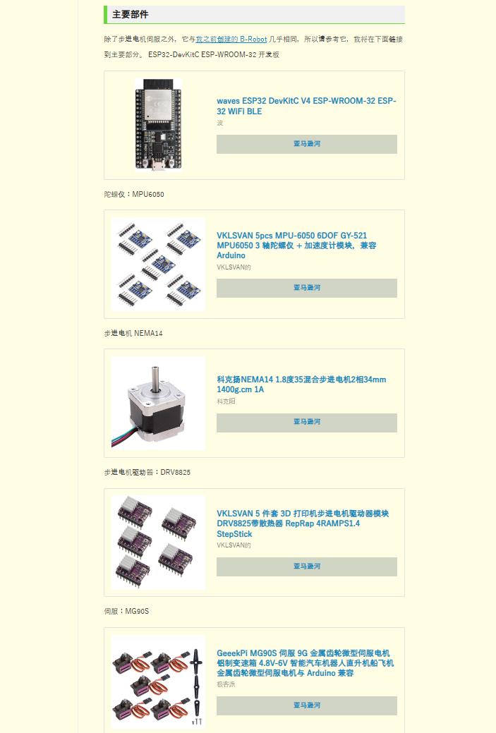
作为之前的改进,对车架进行了审查,增加了伺服系统,并将步进电机改为通用的 NEMA 14。
这款自平衡机器人基于 BROBOT EVO 打造,由 jjrobots 开源,在 B-Robot 论坛上架,但目前链接已死。
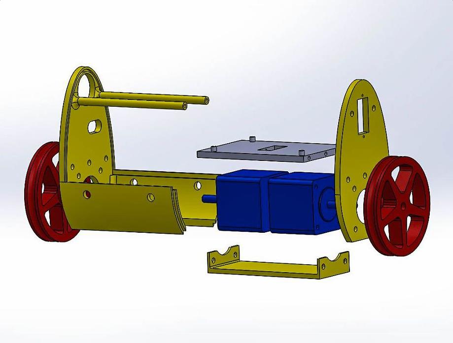
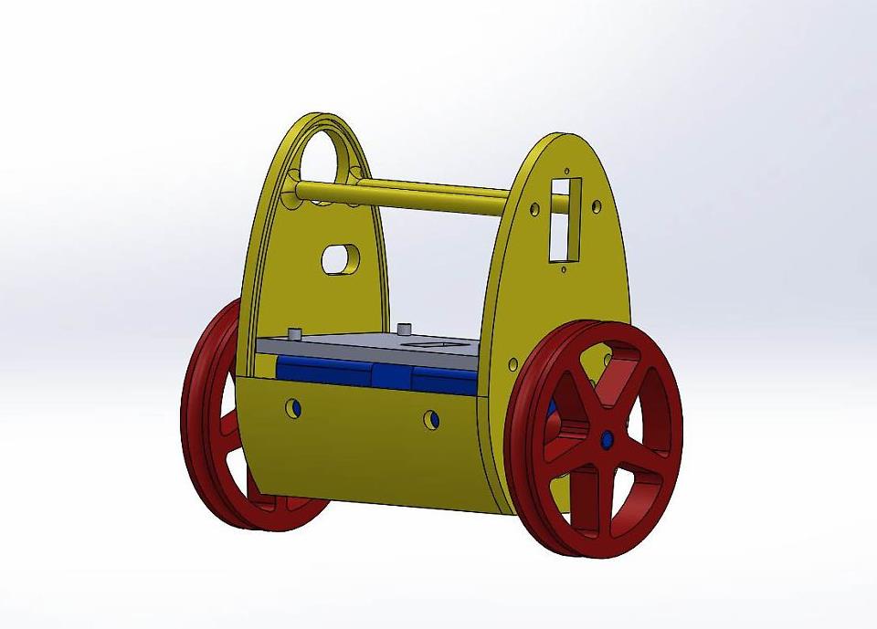
用 3D 打印机制作的框架
框架采用PLA灯丝,由于伺服安装和步进电机规格变化,与之前略有不同,但尺寸几乎相同。 这是开发图和装配的图像。
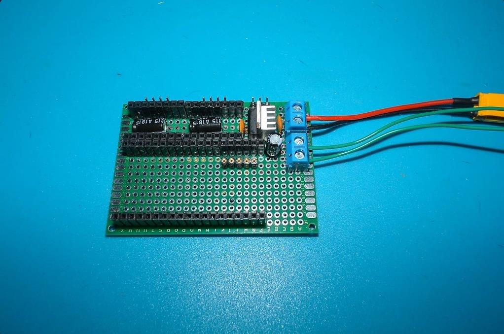
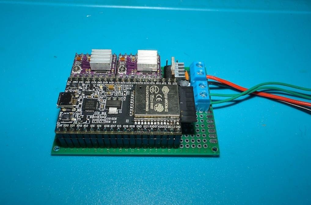
通用板使用 70mm × 50mm。
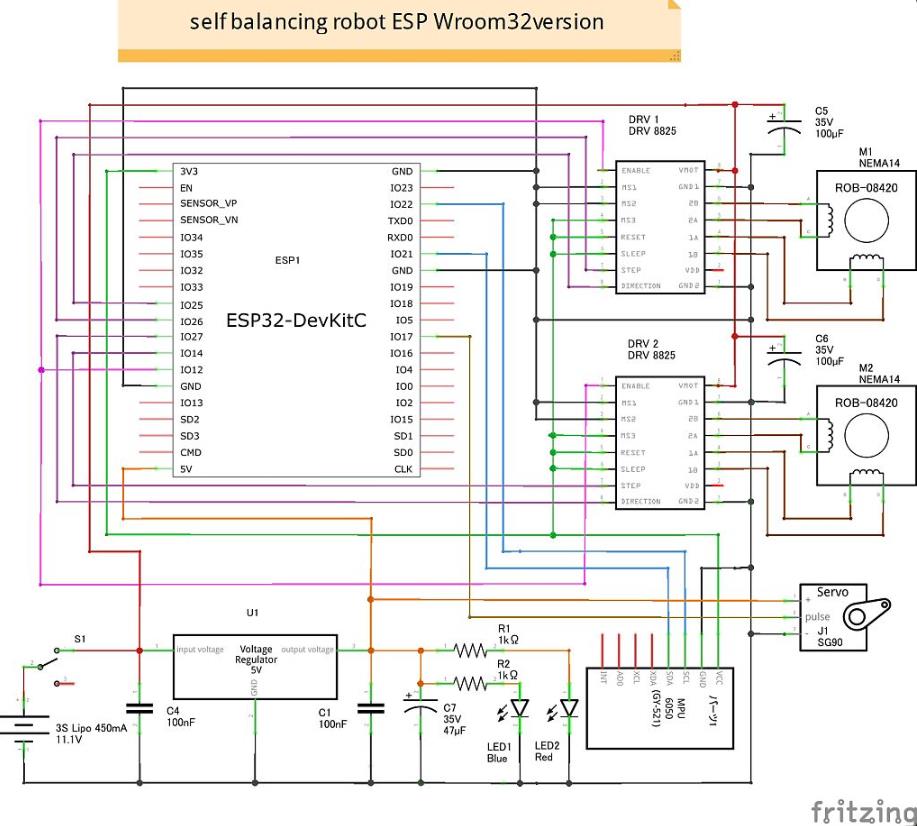
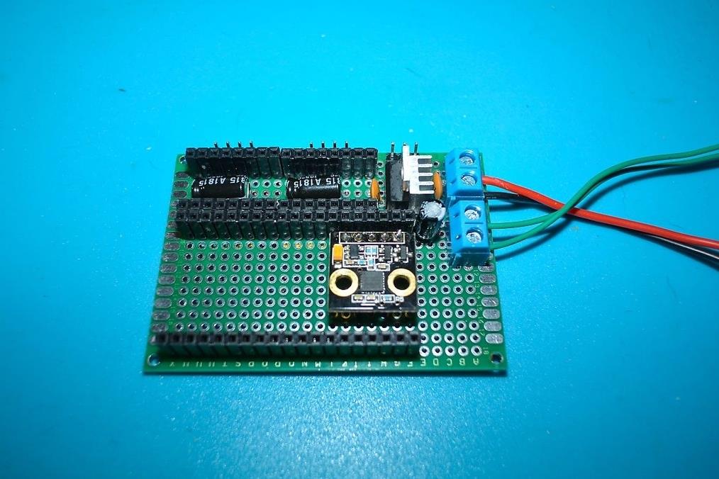
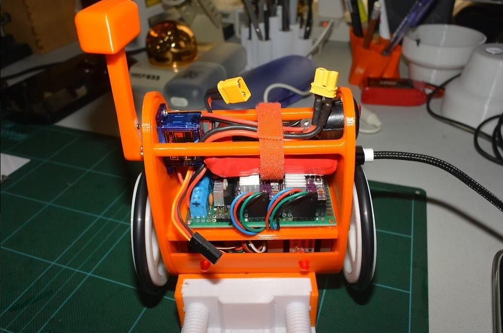
ESP32 和 DRV8825 母头的排针和步进电机和伺服的排针如图所示,短排针母头放在 ESP32 下方进行MPU6050,5V稳压器很热,所以安装了散热器,它的右侧用于电源和开关。它是一个块连接器。
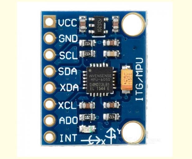
MPU6050使用云台控制器自带的,商用MPU6050上的引脚数量不同,需要注意安装方向。
图片的正面是正向方向,在这个MPU6050的情况下,在这个方向上,在商业MPU6050的情况下,它看起来像下图。
从机架的开发图可以看出,底座用2mm的自攻螺钉安装在板上的板上,步进电机用8mm×3mm的螺钉固定。
切割板板和侧框的 3 毫米丝锥,并用尼龙螺钉固定(如果没有丝锥,3 毫米丝锥也可以)。
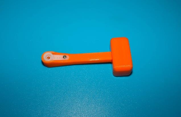
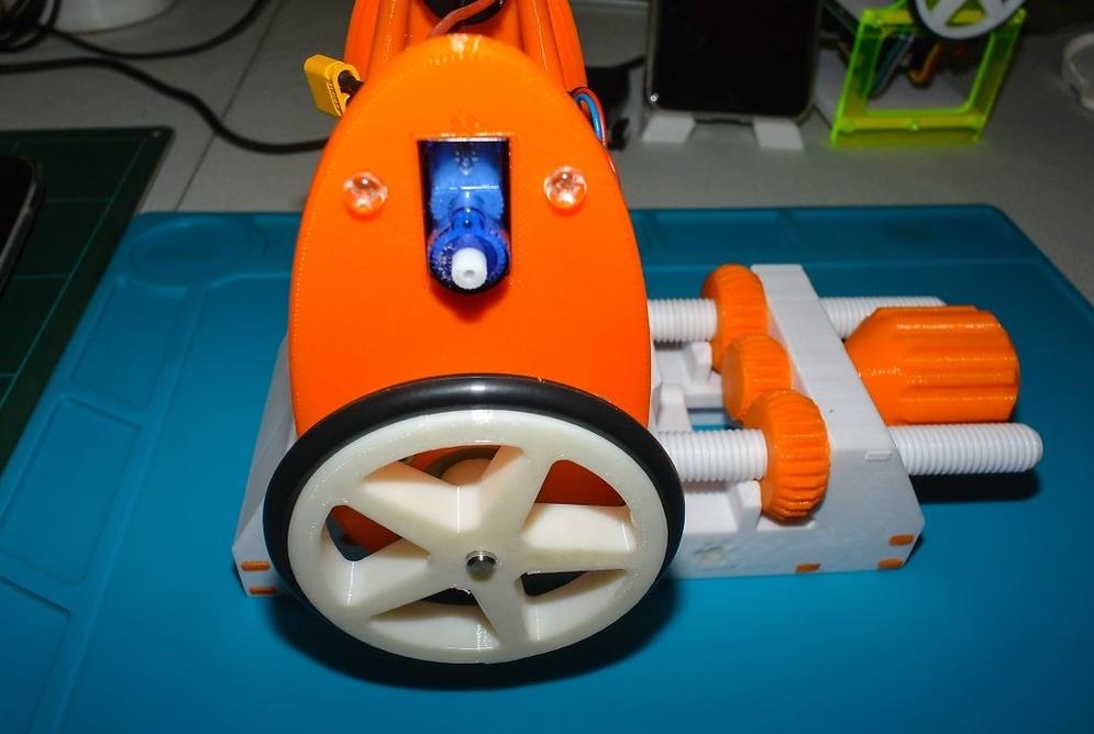
车轮安装有O型圈,切一个3mm的丝锥并用imo螺钉固定在轴上,伺服从背面用2mm的丝锥螺钉固定为SG90,舵机从正面插入MG90S并用丝锥螺钉固定,开关推入。
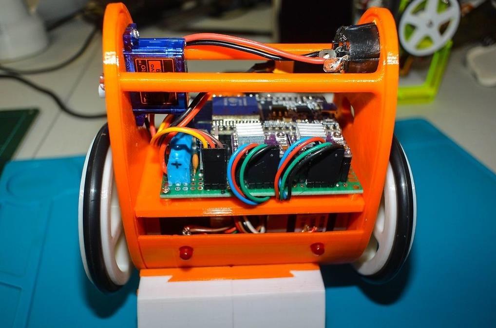
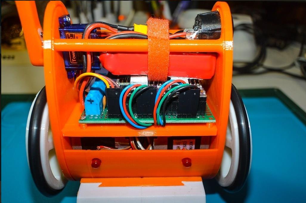
如图所示,电池用魔术贴固定在车架上,顺便说一句,连接器是从左侧开始的,按照伺服、左电机和右电机的顺序(从车身背面看)。
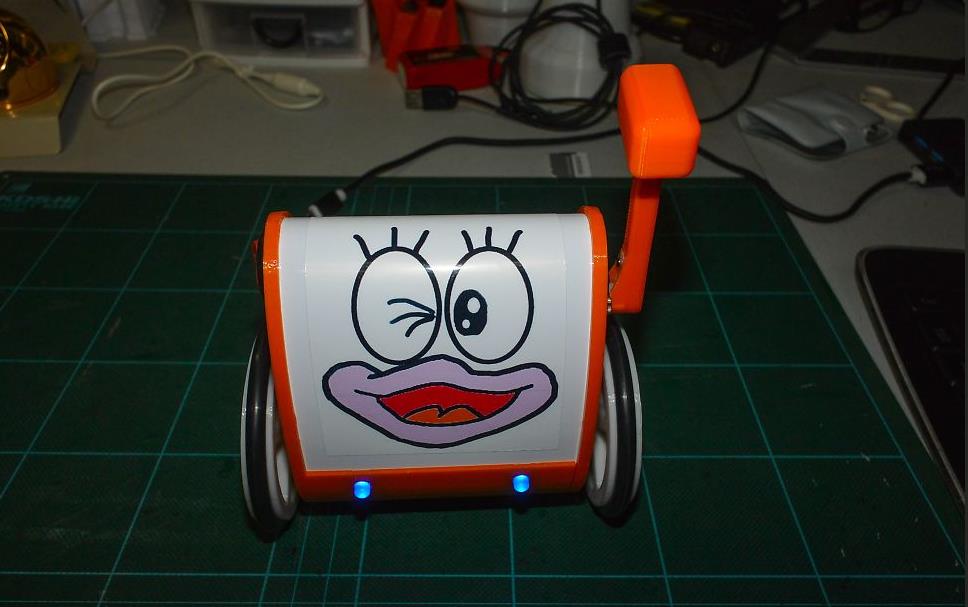
框架盖是一块0.5mm的PVC板,切成83mm×160mm,插入框架的凹槽中,将插图印刷粘贴在印章的印刷纸上。
B-Robot 论坛上发布的文章中有 Github 的链接,所以下载 zip 文件,问题的解决方法也在论坛中讨论,请大家读到最后。
我用Arduino IDE写作,所以是给用过的人准备的,网上有很多方法使用,这里就省略了。
您将需要 ESP32 库。
另外,Arduino IDE版本是Ver1.8.7,编译时出错,所以我使用了Ver1.9.0的测试版。
首先,解压从 Github 下载的 zip 文件,并将生成文件夹中的“BRobotEvo2ESP32”文件夹移动到要与 Arduino 一起使用的文件夹(通常是文档中的 Aruduino 文件夹),尽管该文件夹中有 14 个文件。删除“BRobotEvo2ESP32.ino”,因为它只包含消息,并将“ESP32SelfbalancingBot.CPP”文件重命名为“ESP32SelfbalancingBot.ino”。
另外,论坛上写的缺陷有修复,但我不记得我修复了哪个文件,所以我把这个单元3修改过的文件放在一起,做成一个Zip文件,所以我会上传它们。
B-Robot_ESP32_ZIP_file
在写草图之前,请拆下伺服连接器和电池,以防止不必要的作。
步进电机驱动器电流值调整
写入成功完成后,调整步进电机驱动器的电流值,首先在舵机和左右步进电机连接器断开的情况下测量电流值。就这个机器人而言,它的电流约为150mA
断电后,连接一个步进电机,接通电源,步进电机运行时的电流值通过驱动模块上的音量调节到250mA左右,另一个也以同样的方式调节。
这个现值对我来说刚刚好,但可能存在个体差异,所以还是实际作调整一下比较好,调整完成后,连接好所有连接器,躺着打开电源,过一会儿车轮会微微移动,当运动停止时,慢慢抬起车身,它就会站起来。
在智能手机上进行控制
jjrobots 发布了一个适用于 Android 和 iOS 的应用程序,我使用的是 Android 智能手机,所以我从 Google Play 安装了该应用程序。
当您打开 B-Robot 时,智能手机的 WiFi 设置列表中会显示“Bbot”,选择它,输入密码“12345678”,然后连接。
启动应用程序并选择“B-ROBOT EVO2”进行控制。
伺服系统可以通过右侧的按钮进行作,PID 可以通过智能手机的设置屏幕进行调整。
*笔记
如果在机器人站立时连接智能手机,作会停止片刻,机器人会摔倒,所以在机器人倒下时将智能手机连接到WiFi,然后让机器人站起来,然后在能够用智能手机控制它后让机器人站起来。
项目代码
#include <Arduino.h>
#include <WiFi.h>
#include <WiFiClient.h>
#include <ArduinoOTA.h>
#include <Wire.h>
#include "MPU6050.h"
#include <stdio.h>
#include "esp_types.h"
#include "soc/timer_group_struct.h"
#include "driver/periph_ctrl.h"
#include "driver/timer.h"
#include "driver/ledc.h"
#include "defines.h"
#include "globals.h"
#include "Motors.h"
#include "Control.h"
#include <WiFiUdp.h>
#include "OSC.h"
#include "esp32-hal-ledc.h"

void initTimers();

void initWifiAP() {
	//Serial.println("Setting up WiFi AP...");
	if (WiFi.softAP("bbot", "12345678")) {
		Serial.println("Wifi AP set up successfully");
	}
	WiFi.softAPConfig(IPAddress(192, 168, 4, 1), IPAddress(192, 168, 4, 1),
			IPAddress(255, 255, 255, 0));
}

void initMPU6050() {
	MPU6050_setup();
	delay(500);
	MPU6050_calibrate();
}

void setup() {
	pinMode(PIN_ENABLE_MOTORS, OUTPUT);
	digitalWrite(PIN_ENABLE_MOTORS, HIGH);

	pinMode(PIN_MOTOR1_DIR, OUTPUT);
	pinMode(PIN_MOTOR1_STEP, OUTPUT);
	pinMode(PIN_MOTOR2_DIR, OUTPUT);
	pinMode(PIN_MOTOR2_STEP, OUTPUT);

	pinMode(PIN_SERVO, OUTPUT);

	ledcSetup(6, 50, 16); // channel 6, 50 Hz, 16-bit width
	ledcAttachPin(PIN_SERVO, 6);   // GPIO 22 assigned to channel 1
	delay(50);
	ledcWrite(6, SERVO_AUX_NEUTRO);

	Serial.begin(115200);

	Wire.begin();

	initWifiAP();

	initMPU6050();
	initTimers();

	OSC_init();

	digitalWrite(PIN_ENABLE_MOTORS, LOW);
	for (uint8_t k = 0; k < 5; k++) {
		setMotorSpeedM1(5);
		setMotorSpeedM2(5);
		ledcWrite(6, SERVO_AUX_NEUTRO + 250);
		delay(200);
		setMotorSpeedM1(-5);
		setMotorSpeedM2(-5);
		ledcWrite(6, SERVO_AUX_NEUTRO - 250);
		delay(200);
	}
	ledcWrite(6, SERVO_AUX_NEUTRO);

	digitalWrite(PIN_ENABLE_MOTORS, HIGH);
}

void processOSCMsg() {
	if (OSCpage == 1) {
		if (modifing_control_parameters)  // We came from the settings screen
		{
			OSCfader[0] = 0.5; // default neutral values
			OSCfader[1] = 0.5;
			OSCtoggle[0] = 0;  // Normal mode
			mode = 0;
			modifing_control_parameters = false;
		}

		if (OSCmove_mode) {
			//Serial.print("M ");
			//Serial.print(OSCmove_speed);
			//Serial.print(" ");
			//Serial.print(OSCmove_steps1);
			//Serial.print(",");
			//Serial.println(OSCmove_steps2);
			positionControlMode = true;
			OSCmove_mode = false;
			target_steps1 = steps1 + OSCmove_steps1;
			target_steps2 = steps2 + OSCmove_steps2;
		} else {
			positionControlMode = false;
			throttle = (OSCfader[0] - 0.5) * max_throttle;
			// We add some exponential on steering to smooth the center band
			steering = OSCfader[1] - 0.5;
			if (steering > 0)
				steering = (steering * steering + 0.5 * steering)
						* max_steering;
			else
				steering = (-steering * steering + 0.5 * steering)
						* max_steering;
		}

		if ((mode == 0) && (OSCtoggle[0])) {
			// Change to PRO mode
			max_throttle = MAX_THROTTLE_PRO;
			max_steering = MAX_STEERING_PRO;
			max_target_angle = MAX_TARGET_ANGLE_PRO;
			mode = 1;
		}
		if ((mode == 1) && (OSCtoggle[0] == 0)) {
			// Change to NORMAL mode
			max_throttle = MAX_THROTTLE;
			max_steering = MAX_STEERING;
			max_target_angle = MAX_TARGET_ANGLE;
			mode = 0;
		}
	} else if (OSCpage == 2) { // OSC page 2
		if (!modifing_control_parameters) {
			for (uint8_t i = 0; i < 4; i++)
				OSCfader[i] = 0.5;
			OSCtoggle[0] = 0;

			modifing_control_parameters = true;
			OSC_MsgSend("$P2", 4);
		}
		// User could adjust KP, KD, KP_THROTTLE and KI_THROTTLE (fadder1,2,3,4)
		// Now we need to adjust all the parameters all the times because we dont know what parameter has been moved
		Kp_user = KP * 2 * OSCfader[0];
		Kd_user = KD * 2 * OSCfader[1];
		Kp_thr_user = KP_THROTTLE * 2 * OSCfader[2];
		Ki_thr_user = KI_THROTTLE * 2 * OSCfader[3];
		// Send a special telemetry message with the new parameters
		char auxS[50];
		sprintf(auxS, "$tP,%d,%d,%d,%d", int(Kp_user * 1000),
				int(Kd_user * 1000), int(Kp_thr_user * 1000),
				int(Ki_thr_user * 1000));
		OSC_MsgSend(auxS, 50);

#if DEBUG>0
		Serial.print("Par: ");
		Serial.print(Kp_user);
		Serial.print(" ");
		Serial.print(Kd_user);
		Serial.print(" ");
		Serial.print(Kp_thr_user);
		Serial.print(" ");
		Serial.println(Ki_thr_user);
#endif

		// Calibration mode??
		if (OSCpush[2] == 1) {
			Serial.print("Calibration MODE ");
			angle_offset = angle_adjusted_filtered;
			Serial.println(angle_offset);
		}

		// Kill robot => Sleep
		while (OSCtoggle[0] == 1) {
			//Reset external parameters
			PID_errorSum = 0;
			timer_old = millis();
			setMotorSpeedM1(0);
			setMotorSpeedM2(0);
			digitalWrite(PIN_ENABLE_MOTORS, HIGH);  // Disable motors
			OSC_MsgRead();
		}
	}
}

void loop() {
	OSC_MsgRead();

	if (OSCnewMessage) {
		OSCnewMessage = 0;
		processOSCMsg();
	}

	timer_value = micros();

	if (MPU6050_newData()) {
		MPU6050_read_3axis();

		loop_counter++;
		slow_loop_counter++;
		dt = (timer_value - timer_old) * 0.000001; // dt in seconds
		timer_old = timer_value;

		angle_adjusted_Old = angle_adjusted;
		// Get new orientation angle from IMU (MPU6050)
		float MPU_sensor_angle = MPU6050_getAngle(dt);
		angle_adjusted = MPU_sensor_angle + angle_offset;
		if ((MPU_sensor_angle > -15) && (MPU_sensor_angle < 15))
			angle_adjusted_filtered = angle_adjusted_filtered * 0.99
					+ MPU_sensor_angle * 0.01;

#if DEBUG==1
		Serial.print(dt);
		Serial.print(" ");
		Serial.print(angle_offset);
		Serial.print(" ");
		Serial.print(angle_adjusted);
		Serial.print(",");
		Serial.println(angle_adjusted_filtered);
#endif
		//Serial.print("\t");

		// We calculate the estimated robot speed:
		// Estimated_Speed = angular_velocity_of_stepper_motors(combined) - angular_velocity_of_robot(angle measured by IMU)
		actual_robot_speed = (speed_M1 + speed_M2) / 2; // Positive: forward

		int16_t angular_velocity = (angle_adjusted - angle_adjusted_Old) * 25.0; // 25 is an empirical extracted factor to adjust for real units
		int16_t estimated_speed = -actual_robot_speed + angular_velocity;
		estimated_speed_filtered = estimated_speed_filtered * 0.9
				+ (float) estimated_speed * 0.1; // low pass filter on estimated speed

#if DEBUG==2
				Serial.print(angle_adjusted);
				Serial.print(" ");
				Serial.println(estimated_speed_filtered);
#endif

		if (positionControlMode) {
			// POSITION CONTROL. INPUT: Target steps for each motor. Output: motors speed
			motor1_control = positionPDControl(steps1, target_steps1,
					Kp_position, Kd_position, speed_M1);
			motor2_control = positionPDControl(steps2, target_steps2,
					Kp_position, Kd_position, speed_M2);

			// Convert from motor position control to throttle / steering commands
			throttle = (motor1_control + motor2_control) / 2;
			throttle = constrain(throttle, -190, 190);
			steering = motor2_control - motor1_control;
			steering = constrain(steering, -50, 50);
		}

		// ROBOT SPEED CONTROL: This is a PI controller.
		//    input:user throttle(robot speed), variable: estimated robot speed, output: target robot angle to get the desired speed
		target_angle = speedPIControl(dt, estimated_speed_filtered, throttle,
				Kp_thr, Ki_thr);
		target_angle = constrain(target_angle, -max_target_angle,
				max_target_angle); // limited output

#if DEBUG==3
		Serial.print(angle_adjusted);
		Serial.print(" ");
		Serial.print(estimated_speed_filtered);
		Serial.print(" ");
		Serial.println(target_angle);
#endif

		// Stability control (100Hz loop): This is a PD controller.
		//    input: robot target angle(from SPEED CONTROL), variable: robot angle, output: Motor speed
		//    We integrate the output (sumatory), so the output is really the motor acceleration, not motor speed.
		control_output += stabilityPDControl(dt, angle_adjusted, target_angle,
				Kp, Kd);
		control_output = constrain(control_output, -MAX_CONTROL_OUTPUT,
				MAX_CONTROL_OUTPUT); // Limit max output from control

		// The steering part from the user is injected directly to the output
		motor1 = control_output + steering;
		motor2 = control_output - steering;

		// Limit max speed (control output)
		motor1 = constrain(motor1, -MAX_CONTROL_OUTPUT, MAX_CONTROL_OUTPUT);
		motor2 = constrain(motor2, -MAX_CONTROL_OUTPUT, MAX_CONTROL_OUTPUT);

		int angle_ready;
		if (OSCpush[0])     // If we press the SERVO button we start to move
			angle_ready = 82;
		else
			angle_ready = 74;  // Default angle
		if ((angle_adjusted < angle_ready) && (angle_adjusted > -angle_ready)) // Is robot ready (upright?)
				{
			// NORMAL MODE
			digitalWrite(PIN_ENABLE_MOTORS, LOW);  // Motors enable
			// NOW we send the commands to the motors
			setMotorSpeedM1(motor1);
			setMotorSpeedM2(motor2);
		} else   // Robot not ready (flat), angle > angle_ready => ROBOT OFF
		{
			digitalWrite(PIN_ENABLE_MOTORS, HIGH);  // Disable motors
			setMotorSpeedM1(0);
			setMotorSpeedM2(0);
			PID_errorSum = 0;  // Reset PID I term
			Kp = KP_RAISEUP;   // CONTROL GAINS FOR RAISE UP
			Kd = KD_RAISEUP;
			Kp_thr = KP_THROTTLE_RAISEUP;
			Ki_thr = KI_THROTTLE_RAISEUP;
			// RESET steps
			steps1 = 0;
			steps2 = 0;
			positionControlMode = false;
			OSCmove_mode = false;
			throttle = 0;
			steering = 0;
		}
		// Push1 Move servo arm
		if (OSCpush[0])  // Move arm
		{
			if (angle_adjusted > -40)
				ledcWrite(6, SERVO_MIN_PULSEWIDTH);
			else
				ledcWrite(6, SERVO_MAX_PULSEWIDTH);
		} else
			ledcWrite(6, SERVO_AUX_NEUTRO);

		// Servo2
		//ledcWrite(6, SERVO2_NEUTRO + (OSCfader[2] - 0.5) * SERVO2_RANGE);

		// Normal condition?
		if ((angle_adjusted < 56) && (angle_adjusted > -56)) {
			Kp = Kp_user;            // Default user control gains
			Kd = Kd_user;
			Kp_thr = Kp_thr_user;
			Ki_thr = Ki_thr_user;
		} else // We are in the raise up procedure => we use special control parameters
		{
			Kp = KP_RAISEUP;         // CONTROL GAINS FOR RAISE UP
			Kd = KD_RAISEUP;
			Kp_thr = KP_THROTTLE_RAISEUP;
			Ki_thr = KI_THROTTLE_RAISEUP;
		}

	} // End of new IMU data

	// Medium loop 7.5Hz
	if (loop_counter >= 15) {
		loop_counter = 0;
		// Telemetry here?
#if TELEMETRY_ANGLE==1
		char auxS[25];
		int ang_out = constrain(int(angle_adjusted * 10), -900, 900);
		sprintf(auxS, "$tA,%+04d", ang_out);
		OSC_MsgSend(auxS, 25);
#endif
#if TELEMETRY_DEBUG==1
		char auxS[50];
		sprintf(auxS, "$tD,%d,%d,%ld", int(angle_adjusted * 10), int(estimated_speed_filtered), steps1);
		OSC_MsgSend(auxS, 50);
#endif

	} // End of medium loop
	else if (slow_loop_counter >= 100) // 1Hz
			{
		slow_loop_counter = 0;
		// Read  status
#if TELEMETRY_BATTERY==1
		BatteryValue = (BatteryValue + BROBOT_readBattery(false)) / 2;
		sendBattery_counter++;
		if (sendBattery_counter >= 3) { //Every 3 seconds we send a message
			sendBattery_counter = 0;
			Serial.print("B");
			Serial.println(BatteryValue);
			char auxS[25];
			sprintf(auxS, "$tB,%04d", BatteryValue);
			OSC_MsgSend(auxS, 25);
		}
#endif
	}  // End of slow loop
}
【Arduino 动手做】B-Robot ESP32 版本 Unit 3 自平衡机器人
项目链接:
https://blogdaichan.hatenablog.com/entry/%3Fp%3D7129
https://blogdaichan.hatenablog.com/entry/%3Fp%3D7165
项目作者:大酱(id:blogdaichan)
项目视频:https://www.youtube.com/watch?v=42CqTkvmGMg
项目代码:https://github.com/ghmartin77/B-ROBOT_EVO2_ESP32
https://github.com/ghmartin77/B-ROBOT_EVO2_ESP32/blob/master/BRobotEvo2ESP32/ESP32SelfbalancingBot.cpp
https://drive.google.com/file/d/1mPW7OObvRVnkpS-6l-aGJaYy3k2D7bsu/view
3D打印文件:https://drive.google.com/file/d/1ec8WGoU-F8mJtrSDKjlTmDEM9zWmjJbQ/view


 他的勋章
他的勋章

评论