 返回首页
返回首页
 回到顶部
回到顶部
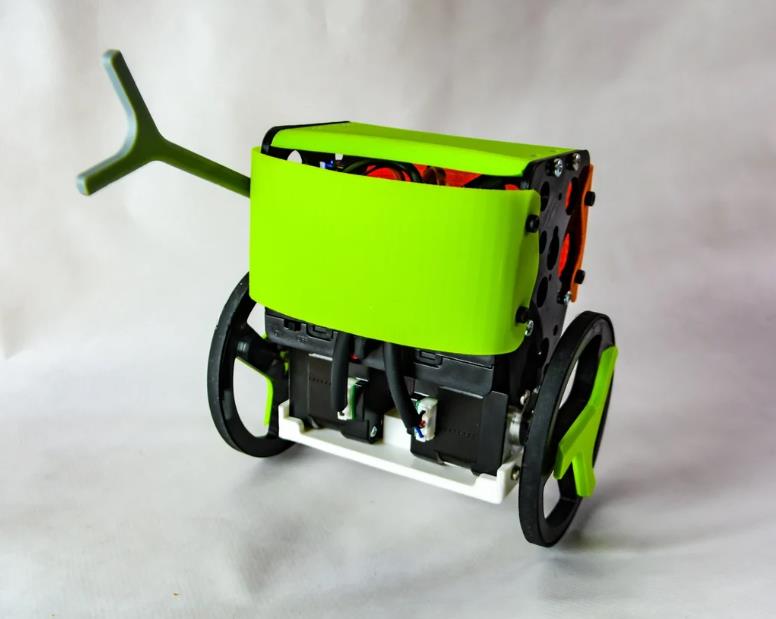
B-robot EVO 2:
极快、稳定、可定制的自平衡机器人。检查机器人的运行情况!
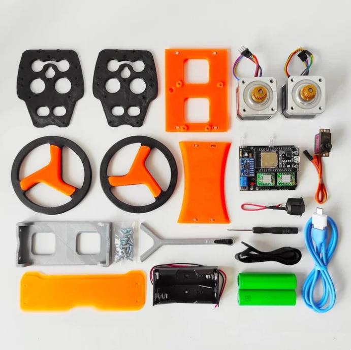
零件清单
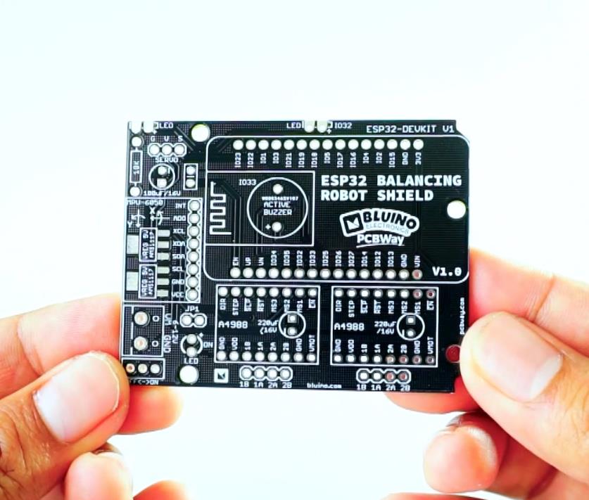
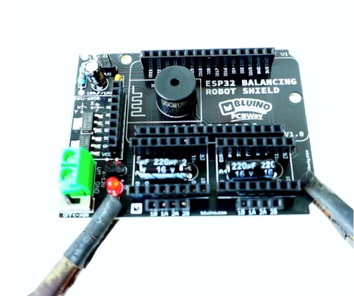
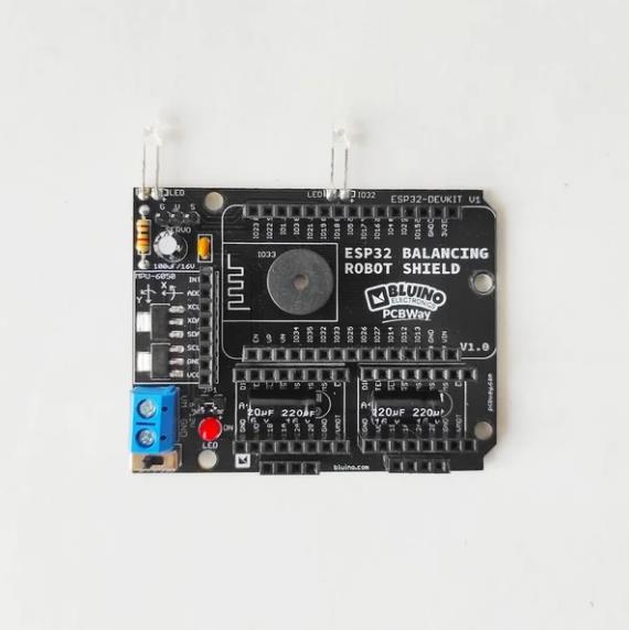
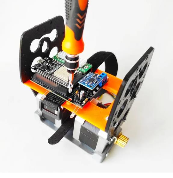
1 x PCB ESP32 平衡机器人防护罩 (https://www.pcbway.com/project/shareproject/ESP32_Balancing_Robot_Shield.html)
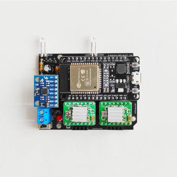
1 个 ESP32 DEVKIT V1 板
2 x 步进电机驱动器 A4988
1 x 3 轴传感器和陀螺仪传感器MPU6050
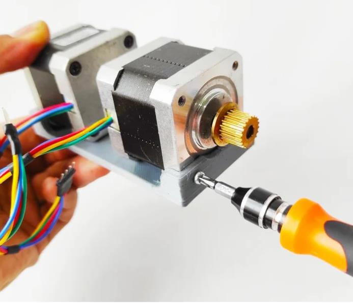
2 x 步进电机 Nema17
1 x 伺服电机 MG90S
1 x LED 3 毫米
2 x LED 3mm 白色超亮
1 x 有源 BUzzer
2 x V 稳压器 5V AMS1117 (SMD)
1 x 电阻器 1K 欧姆
1 x 电容器 0.1uF
1 x 电容器 100uF/16V
2 x 电容器 220uF/16V
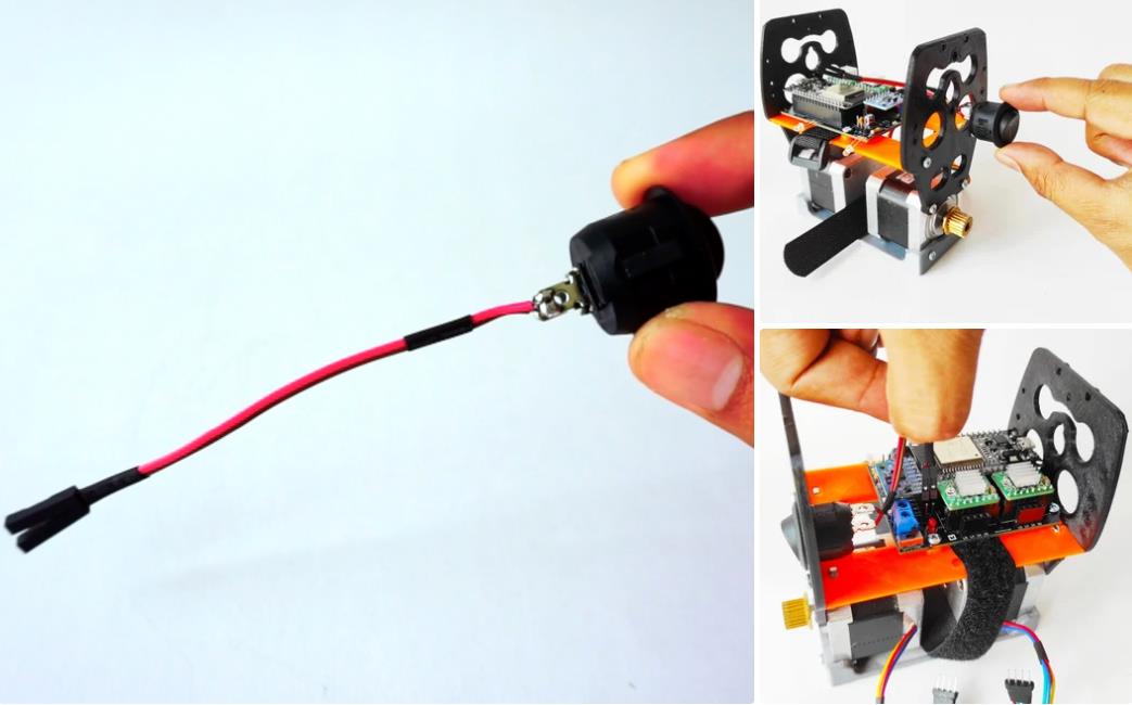
1 x 翘板开关直径 20 毫米
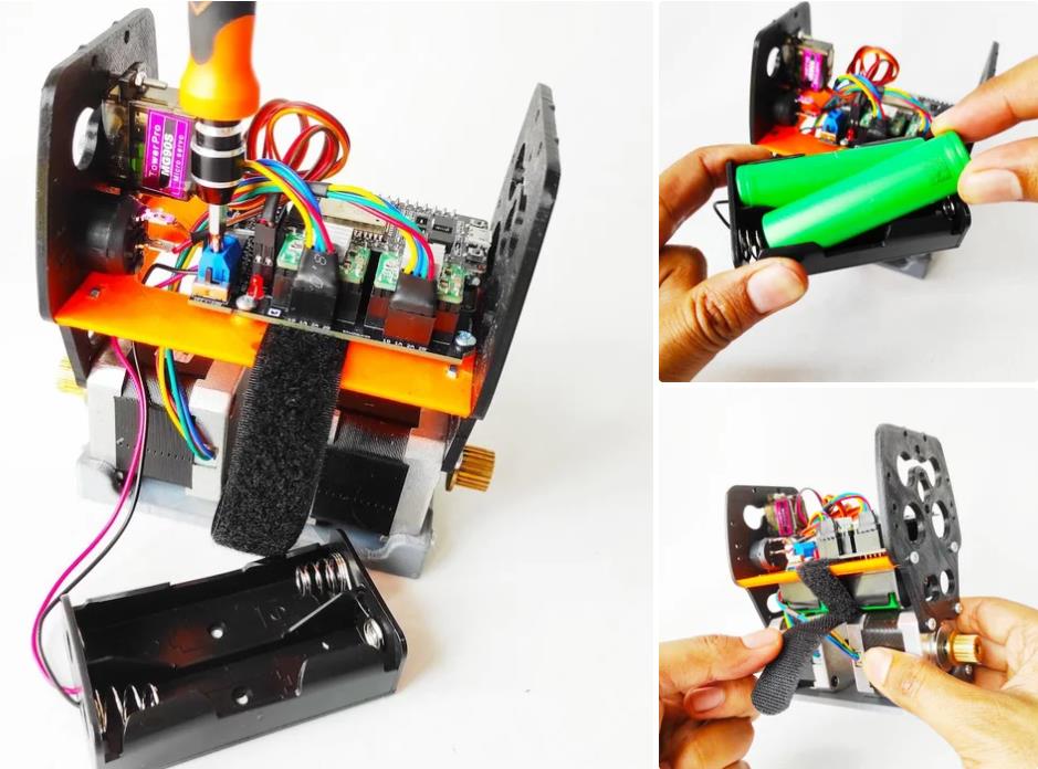
2 x 锂离子电池 18650 3,7V
1 x 电池座 2x 18650
1 x 微型 USB 数据线
1 x OTG 适配器
1 x 端子螺钉 2 针 5mm
2 x 母头 15 针
5 x 母头 8 针
2 x 母头 4 针
1 x 公头 2 针
1 x 公头接头 3 针
1 x 跳线帽
1 x 固定螺钉 5mm
1 x 套装 M3 固定螺钉 10mm
2 x O 形圈 3mm 内径 82mm
1 x 套装 3D 打印零件
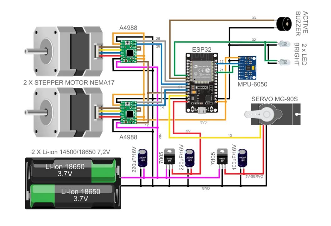
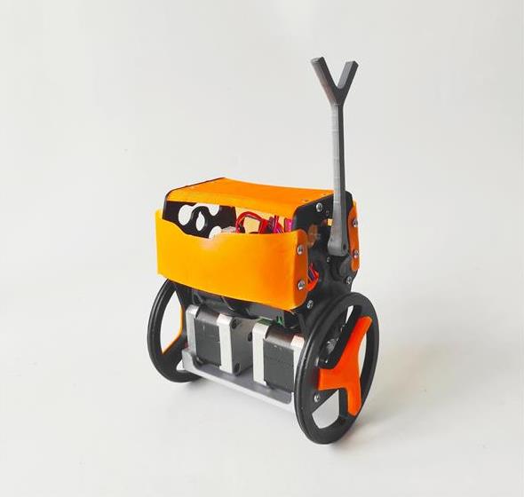
B-robot EVO 2 是一款开源、基于 arduino 的自平衡机器人,具有许多功能(看看下面的描述)现在带有战斗臂和附加组件来与另一个机器人战斗(或在您跌倒时站起来)。
使用智能手机或平板电脑 (WIFI) 进行远程控制。
该机器人是 B-robot ORIGINAL 的自然演变,并使用创建所需的相同电子设备和电机:
空气曲棍球机器人
Sphere-O-Bot (蛋机器人 MOD)
iBoard机器人
PyBot 机械臂
相机滑块机器人
厌倦了一台机器人?创建另一个仅打印 3D 零件!
B-robot EVO 2 是一款基于 Arduino 的机器人。开放的软件和硬件创建。您可以轻松修改其行为,在 Arduino CODE 中或通过 CONTROL APP 实时更改加速度/速度/稳定性参数。
新功能:
通过 GOOGLE PLAY 上的免费应用程序使用智能手机/平板电脑控制它(适用于 Android 或适用于 iOS 设备的 Apple 商店
谷歌块可控!
非常适合在学习机器人技术时获得乐趣(看看机器人挑战!
现在可以使用普通 AA 电池(或 3 芯锂聚合物电池)
二 SERVO 输出(一个用于 ARM)
更易于打印,使用更少的塑料
PRO MODE 可以从您的智能手机/平板电脑激活(提高敏捷性和速度)
增加 WIFI范围(最远40米)
新功能:使用 Thingiverse 定制器创建您自己的保险杠!
新增功能: 用于丁腈 O 形圈的新车轮型号 [V11]
新增功能: 全新 100% 正面和背面 3D 打印保险杠“BUMPER 3D 打印 V1”
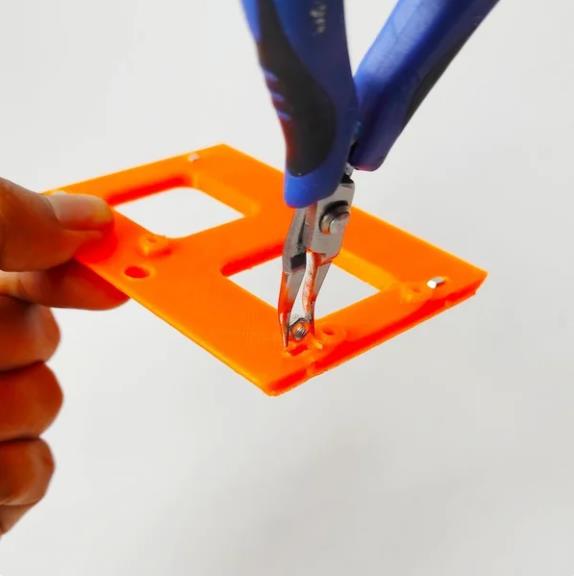
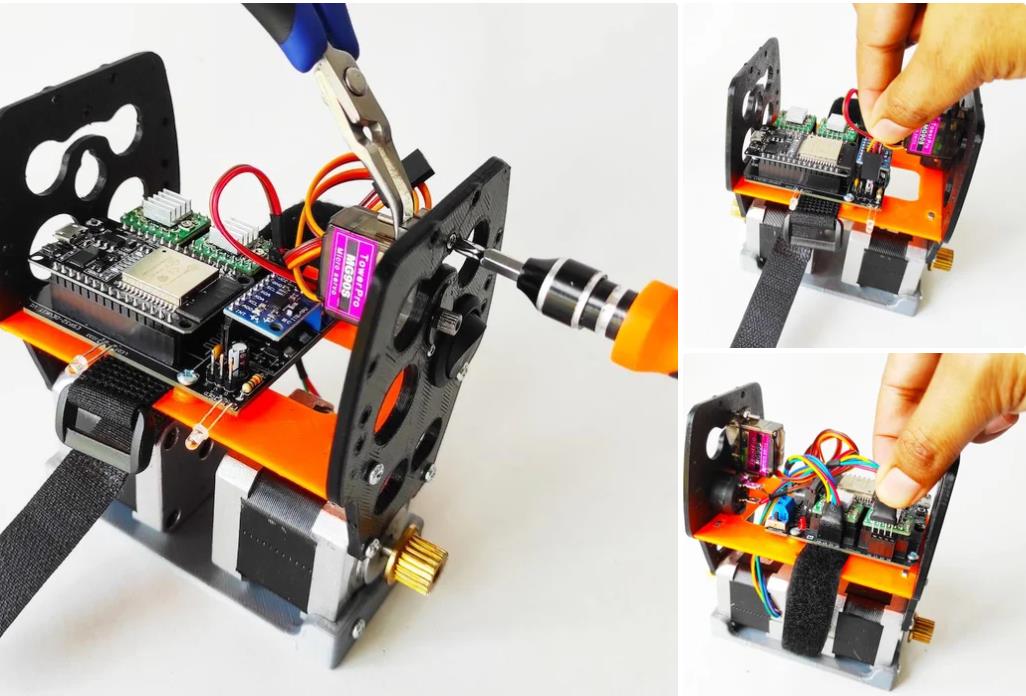
您需要打印的内容:
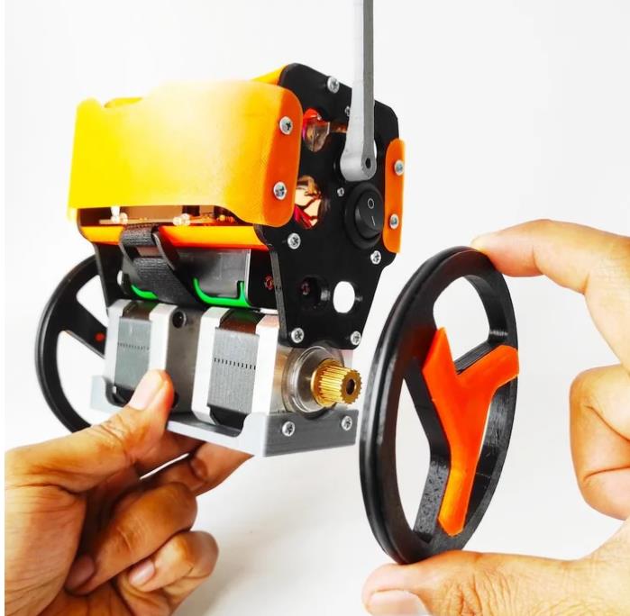
2x 轮子
2x 集线器
手臂
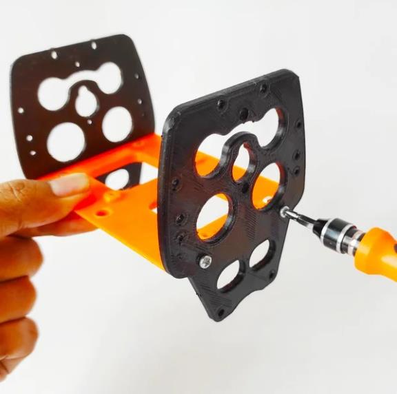
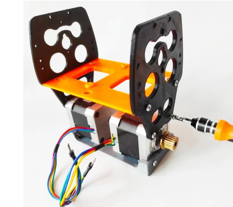
2x 侧面板
顶层货架
电机架
电子货架
2x 保险杠(要创建您的定制保险杠,请点击此链接)
--------------------------------------------------
附加组件:
可选:2x 保险杠(顶部前保险杠)
自选:战斗手臂:雷神之锤
自选:战斗武器:战斧
自选:GoPro 相机支持
自选:汽水罐顶部搁板支撑
自选:O 形圈轮 (x2)

项目代码
/*
 * esp32_wifi_balancing_robot.ino
 *
 *  Created on: 23.02.2021
 *      Author: anonymous
 */

#include <Wire.h>
#include <WiFi.h>
#include <ArduinoOTA.h>
#include <Arduino.h>
#include <AsyncTCP.h>
#include <ESPAsyncWebServer.h>
#include "Control.h"
#include "MPU6050.h"
#include "Motors.h"
#include "defines.h"
#include "globals.h"
#include <stdio.h>
#include "esp_types.h"
#include "soc/timer_group_struct.h"
#include "driver/periph_ctrl.h"
#include "driver/timer.h"
#include "driver/ledc.h"
#include "esp32-hal-ledc.h"

const char* PARAM_FADER1 = "fader1";
const char* PARAM_FADER2 = "fader2";
const char* PARAM_PUSH1 = "push1";
const char* PARAM_PUSH2 = "push2";
const char* PARAM_PUSH3 = "push3";
const char* PARAM_PUSH4 = "push4";
const char* PARAM_TOGGLE1 = "toggle1";
const char* PARAM_FADER3 = "fader3";
const char* PARAM_FADER4 = "fader4";
const char* PARAM_FADER5 = "fader5";
const char* PARAM_FADER6 = "fader6";

/* Wifi Crdentials */
String sta_ssid = "$your_ssid_maximum_32_characters";     // set Wifi network you want to connect to
String sta_password = "$your_pswd_maximum_32_characters";        // set password for Wifi network

unsigned long previousMillis = 0;

AsyncWebServer server(80);

void initMPU6050() {
  MPU6050_setup();
  delay(500);
  MPU6050_calibrate();
}

void initTimers();

void notFound(AsyncWebServerRequest *request) {
  request->send(404, "text/plain", "Not found");
}

void setup() {
  Serial.begin(115200);         // set up seriamonitor at 115200 bps
  Serial.setDebugOutput(true);
  Serial.println();
  Serial.println("*ESP32 Camera Balancing Robot*");
  Serial.println("--------------------------------------------------------");


  pinMode(PIN_ENABLE_MOTORS, OUTPUT);
  digitalWrite(PIN_ENABLE_MOTORS, HIGH);

  pinMode(PIN_MOTOR1_DIR, OUTPUT);
  pinMode(PIN_MOTOR1_STEP, OUTPUT);
  pinMode(PIN_MOTOR2_DIR, OUTPUT);
  pinMode(PIN_MOTOR2_STEP, OUTPUT);
  pinMode(PIN_SERVO, OUTPUT);

  pinMode(PIN_LED, OUTPUT);
  digitalWrite(PIN_LED, LOW);

  pinMode(PIN_WIFI_LED, OUTPUT);
  digitalWrite(PIN_WIFI_LED, LOW);

  pinMode(PIN_BUZZER, OUTPUT);
  digitalWrite(PIN_BUZZER, LOW);

  ledcSetup(6, 50, 16); // channel 6, 50 Hz, 16-bit width
  ledcAttachPin(PIN_SERVO, 6);   // GPIO 22 assigned to channel 1
  delay(50);
  ledcWrite(6, SERVO_AUX_NEUTRO);

  Wire.begin();
  initMPU6050();

  // Set NodeMCU Wifi hostname based on chip mac address
  char chip_id[15];
  snprintf(chip_id, 15, "%04X", (uint16_t)(ESP.getEfuseMac()>>32));
  String hostname = "esp32brobot-" + String(chip_id);

  Serial.println();
  Serial.println("Hostname: "+hostname);

  // first, set NodeMCU as STA mode to connect with a Wifi network
  WiFi.mode(WIFI_STA);
  WiFi.begin(sta_ssid.c_str(), sta_password.c_str());
  Serial.println("");
  Serial.print("Connecting to: ");
  Serial.println(sta_ssid);
  Serial.print("Password: ");
  Serial.println(sta_password);

  // try to connect with Wifi network about 8 seconds
  unsigned long currentMillis = millis();
  previousMillis = currentMillis;
  while (WiFi.status() != WL_CONNECTED && currentMillis - previousMillis <= 8000) {
    delay(500);
    Serial.print(".");
    currentMillis = millis();
  }

  // if failed to connect with Wifi network set NodeMCU as AP mode
  IPAddress myIP;
  if (WiFi.status() == WL_CONNECTED) {
    Serial.println("");
    Serial.println("*WiFi-STA-Mode*");
    Serial.print("IP: ");
    myIP=WiFi.localIP();
    Serial.println(myIP);
    digitalWrite(PIN_WIFI_LED, HIGH);    // Wifi LED on when connected to Wifi as STA mode
    delay(2000);
  } else {
    WiFi.mode(WIFI_AP);
    WiFi.softAP(hostname.c_str());
    myIP = WiFi.softAPIP();
    Serial.println("");
    Serial.println("WiFi failed connected to " + sta_ssid);
    Serial.println("");
    Serial.println("*WiFi-AP-Mode*");
    Serial.print("AP IP address: ");
    Serial.println(myIP);
    digitalWrite(PIN_WIFI_LED, LOW);   // Wifi LED off when status as AP mode
    delay(2000);
  }


  // Send a GET request to <ESP_IP>/?fader=<inputValue>
    server.on("/", HTTP_GET, [] (AsyncWebServerRequest *request) {
    String inputValue;
    String inputMessage;
    OSCnewMessage = 1;

    // Get value for Forward/Backward
    if (request->hasParam(PARAM_FADER1)) {
      OSCpage = 1;
      inputValue = request->getParam(PARAM_FADER1)->value();
      inputMessage = PARAM_FADER1;
      OSCfader[0] = inputValue.toFloat();
    }
    // Get value for Right/Left
    else if (request->hasParam(PARAM_FADER2)) {
      OSCpage = 1;
      inputValue = request->getParam(PARAM_FADER2)->value();
      inputMessage = PARAM_FADER2;
      OSCfader[1] = inputValue.toFloat();
    }
    // Get value for Servo0
    else if (request->hasParam(PARAM_PUSH1)) {
      OSCpage = 1;
      inputValue = request->getParam(PARAM_PUSH1)->value();
      inputMessage = PARAM_PUSH1;
      if(inputValue.equals("1")) OSCpush[0]=1;
      else OSCpush[0]=0;
    }
    // Get value for Setting
    else if (request->hasParam(PARAM_PUSH2)) {
      OSCpage = 2;
      inputValue = request->getParam(PARAM_PUSH2)->value();
      inputMessage = PARAM_PUSH2;
      if(inputValue.equals("1")) OSCpush[2]=1;
      else OSCpush[2]=0;
    }
    // Get value for Buzzer
    else if (request->hasParam(PARAM_PUSH3)) {
      inputValue = request->getParam(PARAM_PUSH3)->value();
      inputMessage = PARAM_PUSH3;
      if(inputValue.equals("1")) {
        digitalWrite(PIN_BUZZER, HIGH);
        delay(150);
        digitalWrite(PIN_BUZZER, LOW);
        delay(80);
        digitalWrite(PIN_BUZZER, HIGH);
        delay(150);
        digitalWrite(PIN_BUZZER, LOW);
        delay(80);
      }
    }
    // Get value for Led
    else if (request->hasParam(PARAM_PUSH4)) {
      inputValue = request->getParam(PARAM_PUSH4)->value();
      inputMessage = PARAM_PUSH4;
      if(inputValue.equals("1")) digitalWrite(PIN_LED, HIGH);
      else digitalWrite(PIN_LED, LOW);
    }
    // Get value for mode PRO
    else if (request->hasParam(PARAM_TOGGLE1)) {
      OSCpage = 1;
      inputValue = request->getParam(PARAM_TOGGLE1)->value();
      inputMessage = PARAM_TOGGLE1;
      if(inputValue.equals("1")) OSCtoggle[0]=1;
      else OSCtoggle[0]=0;
    }
    // Get value for P-Stability
    else if (request->hasParam(PARAM_FADER3)) {
      OSCpage = 2;
      inputValue = request->getParam(PARAM_FADER3)->value();
      inputMessage = PARAM_FADER3;
      OSCfader[0] = inputValue.toFloat();
    }
    // Get value for D-Stability
    else if (request->hasParam(PARAM_FADER4)) {
      OSCpage = 2;
      inputValue = request->getParam(PARAM_FADER4)->value();
      inputMessage = PARAM_FADER4;
      OSCfader[0] = inputValue.toFloat();
    }
    // Get value for P-Speed
    else if (request->hasParam(PARAM_FADER5)) {
      OSCpage = 2;
      inputValue = request->getParam(PARAM_FADER5)->value();
      inputMessage = PARAM_FADER5;
      OSCfader[0] = inputValue.toFloat();
    }
    // Get value for I-Speed
    else if (request->hasParam(PARAM_FADER6)) {
      OSCpage = 2;
      inputValue = request->getParam(PARAM_FADER6)->value();
      inputMessage = PARAM_FADER6;
      OSCfader[0] = inputValue.toFloat();
    }
    else {
      inputValue = "No message sent";
    }
    Serial.println(inputMessage+'='+inputValue);
    request->send(200, "text/text", "");
  });

  server.onNotFound (notFound);    // when a client requests an unknown URI (i.e. something other than "/"), call function "handleNotFound"
  server.begin();                           // actually start the server

  initTimers();

  // default neutral values
  OSCfader[0] = 0.5;
  OSCfader[1] = 0.5;
  OSCfader[2] = 0.5;
  OSCfader[3] = 0.5;

  digitalWrite(PIN_ENABLE_MOTORS, LOW);
  for (uint8_t k = 0; k < 5; k++) {
    setMotorSpeedM1(5);
    setMotorSpeedM2(5);
    ledcWrite(6, SERVO_AUX_NEUTRO + 250);
    delay(200);
    setMotorSpeedM1(-5);
    setMotorSpeedM2(-5);
    ledcWrite(6, SERVO_AUX_NEUTRO - 250);
    delay(200);
  }
  ledcWrite(6, SERVO_AUX_NEUTRO);

  ArduinoOTA.begin();   // enable to receive update/upload firmware via Wifi OTA
}

void loop() {
  ArduinoOTA.handle();

  if (OSCnewMessage) {
    OSCnewMessage = 0;
    processOSCMsg();
  }

  timer_value = micros();

  if (MPU6050_newData()) {

    MPU6050_read_3axis();

    dt = (timer_value - timer_old) * 0.000001; // dt in seconds
    //Serial.println(timer_value - timer_old);
    timer_old = timer_value;

    angle_adjusted_Old = angle_adjusted;
    // Get new orientation angle from IMU (MPU6050)
    float MPU_sensor_angle = MPU6050_getAngle(dt);
    angle_adjusted = MPU_sensor_angle + angle_offset;
    if ((MPU_sensor_angle > -15) && (MPU_sensor_angle < 15))
      angle_adjusted_filtered = angle_adjusted_filtered * 0.99 + MPU_sensor_angle * 0.01;


    // We calculate the estimated robot speed:
    // Estimated_Speed = angular_velocity_of_stepper_motors(combined) - angular_velocity_of_robot(angle measured by IMU)
    actual_robot_speed = (speed_M1 + speed_M2) / 2; // Positive: forward

    int16_t angular_velocity = (angle_adjusted - angle_adjusted_Old) * 25.0; // 25 is an empirical extracted factor to adjust for real units
    int16_t estimated_speed = -actual_robot_speed + angular_velocity;
    estimated_speed_filtered = estimated_speed_filtered * 0.9 + (float) estimated_speed * 0.1; // low pass filter on estimated speed


    if (positionControlMode) {
      // POSITION CONTROL. INPUT: Target steps for each motor. Output: motors speed
      motor1_control = positionPDControl(steps1, target_steps1, Kp_position, Kd_position, speed_M1);
      motor2_control = positionPDControl(steps2, target_steps2, Kp_position, Kd_position, speed_M2);

      // Convert from motor position control to throttle / steering commands
      throttle = (motor1_control + motor2_control) / 2;
      throttle = constrain(throttle, -190, 190);
      steering = motor2_control - motor1_control;
      steering = constrain(steering, -50, 50);
    }

    // ROBOT SPEED CONTROL: This is a PI controller.
    //    input:user throttle(robot speed), variable: estimated robot speed, output: target robot angle to get the desired speed
    target_angle = speedPIControl(dt, estimated_speed_filtered, throttle, Kp_thr, Ki_thr);
    target_angle = constrain(target_angle, -max_target_angle, max_target_angle); // limited output

    // Stability control (100Hz loop): This is a PD controller.
    //    input: robot target angle(from SPEED CONTROL), variable: robot angle, output: Motor speed
    //    We integrate the output (sumatory), so the output is really the motor acceleration, not motor speed.
    control_output += stabilityPDControl(dt, angle_adjusted, target_angle, Kp, Kd);
    control_output = constrain(control_output, -MAX_CONTROL_OUTPUT,  MAX_CONTROL_OUTPUT); // Limit max output from control

    // The steering part from the user is injected directly to the output
    motor1 = control_output + steering;
    motor2 = control_output - steering;

    // Limit max speed (control output)
    motor1 = constrain(motor1, -MAX_CONTROL_OUTPUT, MAX_CONTROL_OUTPUT);
    motor2 = constrain(motor2, -MAX_CONTROL_OUTPUT, MAX_CONTROL_OUTPUT);

    int angle_ready;
    if (OSCpush[0])     // If we press the SERVO button we start to move
      angle_ready = 82;
    else
      angle_ready = 74;  // Default angle
    if ((angle_adjusted < angle_ready) && (angle_adjusted > -angle_ready)) // Is robot ready (upright?)
        {
      // NORMAL MODE
      digitalWrite(PIN_ENABLE_MOTORS, LOW);  // Motors enable
      // NOW we send the commands to the motors
      setMotorSpeedM1(motor1);
      setMotorSpeedM2(motor2);
    } else   // Robot not ready (flat), angle > angle_ready => ROBOT OFF
    {
      digitalWrite(PIN_ENABLE_MOTORS, HIGH);  // Disable motors
      setMotorSpeedM1(0);
      setMotorSpeedM2(0);
      PID_errorSum = 0;  // Reset PID I term
      Kp = KP_RAISEUP;   // CONTROL GAINS FOR RAISE UP
      Kd = KD_RAISEUP;
      Kp_thr = KP_THROTTLE_RAISEUP;
      Ki_thr = KI_THROTTLE_RAISEUP;
      // RESET steps
      steps1 = 0;
      steps2 = 0;
      positionControlMode = false;
      OSCmove_mode = false;
      throttle = 0;
      steering = 0;
    }

    // Push1 Move servo arm
    if (OSCpush[0]) {
      if (angle_adjusted > -40)
        ledcWrite(6, SERVO_MAX_PULSEWIDTH);
      else
        ledcWrite(6, SERVO_MIN_PULSEWIDTH);
    } else
      ledcWrite(6, SERVO_AUX_NEUTRO);

    // Servo2
    //ledcWrite(6, SERVO2_NEUTRO + (OSCfader[2] - 0.5) * SERVO2_RANGE);

    // Normal condition?
    if ((angle_adjusted < 56) && (angle_adjusted > -56)) {
      Kp = Kp_user;            // Default user control gains
      Kd = Kd_user;
      Kp_thr = Kp_thr_user;
      Ki_thr = Ki_thr_user;
    } else // We are in the raise up procedure => we use special control parameters
    {
      Kp = KP_RAISEUP;         // CONTROL GAINS FOR RAISE UP
      Kd = KD_RAISEUP;
      Kp_thr = KP_THROTTLE_RAISEUP;
      Ki_thr = KI_THROTTLE_RAISEUP;
    }

  } // End of new IMU data

}


void processOSCMsg() {
  if (OSCpage == 1) {
    if (modifing_control_parameters)  // We came from the settings screen
    {
      OSCfader[0] = 0.5; // default neutral values
      OSCfader[1] = 0.5; // default neutral values
      OSCtoggle[0] = 0;  // Normal mode
      mode = 0;
      modifing_control_parameters = false;
    }

    if (OSCmove_mode) {
      Serial.print("M ");
      Serial.print(OSCmove_speed);
      Serial.print(" ");
      Serial.print(OSCmove_steps1);
      Serial.print(",");
      Serial.println(OSCmove_steps2);
      positionControlMode = true;
      OSCmove_mode = false;
      target_steps1 = steps1 + OSCmove_steps1;
      target_steps2 = steps2 + OSCmove_steps2;
    } else {
      positionControlMode = false;
      throttle = (OSCfader[0] - 0.5) * max_throttle;
      // We add some exponential on steering to smooth the center band
      steering = OSCfader[1] - 0.5;
      if (steering > 0)
        steering = (steering * steering + 0.5 * steering) * max_steering;
      else
        steering = (-steering * steering + 0.5 * steering) * max_steering;
    }

    if ((mode == 0) && (OSCtoggle[0])) {
      // Change to PRO mode
      max_throttle = MAX_THROTTLE_PRO;
      max_steering = MAX_STEERING_PRO;
      max_target_angle = MAX_TARGET_ANGLE_PRO;
      mode = 1;
    }
    if ((mode == 1) && (OSCtoggle[0] == 0)) {
      // Change to NORMAL mode
      max_throttle = MAX_THROTTLE;
      max_steering = MAX_STEERING;
      max_target_angle = MAX_TARGET_ANGLE;
      mode = 0;
    }
  } else if (OSCpage == 2) { // OSC page 2
    if (!modifing_control_parameters) {
      for (uint8_t i = 0; i < 4; i++)
        OSCfader[i] = 0.5;
      OSCtoggle[0] = 0;

      modifing_control_parameters = true;
      //OSC_MsgSend("$P2", 4);
    }
    // User could adjust KP, KD, KP_THROTTLE and KI_THROTTLE (fadder3,4,5,6)
    // Now we need to adjust all the parameters all the times because we dont know what parameter has been moved
    Kp_user = KP * 2 * OSCfader[0];
    Kd_user = KD * 2 * OSCfader[1];
    Kp_thr_user = KP_THROTTLE * 2 * OSCfader[2];
    Ki_thr_user = KI_THROTTLE * 2 * OSCfader[3];
    // Send a special telemetry message with the new parameters
    char auxS[50];
    sprintf(auxS, "$tP,%d,%d,%d,%d", int(Kp_user * 1000), int(Kd_user * 1000), int(Kp_thr_user * 1000), int(Ki_thr_user * 1000));
    //OSC_MsgSend(auxS, 50);


    // Calibration mode??
    if (OSCpush[2] == 1) {
      Serial.print("Calibration MODE ");
      angle_offset = angle_adjusted_filtered;
      Serial.println(angle_offset);
    }

    // Kill robot => Sleep
    while (OSCtoggle[0] == 1) {
      //Reset external parameters
      PID_errorSum = 0;
      timer_old = millis();
      setMotorSpeedM1(0);
      setMotorSpeedM2(0);
      digitalWrite(PIN_ENABLE_MOTORS, HIGH);  // Disable motors
    }
  }
}
【Arduino 动手做】DIY ESP32 Wifi 自平衡机器人 - B-Robot ESP32 Arduino 编程
项目链接:https://www.instructables.com/DIY-ESP32-Wifi-Self-Balancing-Robot-B-Robot-ESP32-/
项目作者:bluino_electronics
参考资料:https://blogdaichan.hatenablog.com/entry/%3Fp%3D7129
项目视频:https://www.youtube.com/watch?v=tZynIj1StpM
项目代码:https://github.com/bluino/esp32_wifi_balancing_robot
3D打印文件:https://www.thingiverse.com/thing:2306541
PCB项目链接:https://www.pcbway.com/project/shareproject/ESP32_Balancing_Robot_Shield.html
Android 应用程序:https://play.google.com/store/apps/details?id=com.bluino.esp32wifibalancingrobot


 他的勋章
他的勋章

评论