 返回首页
返回首页
 回到顶部
回到顶部
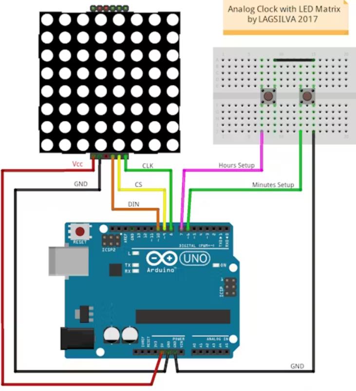
这是我关于 LED 矩阵和 Arduino 上的模拟时钟的项目。
带MAX7219的 LED 矩阵用途广泛,可用于 Arduino 的多个项目。
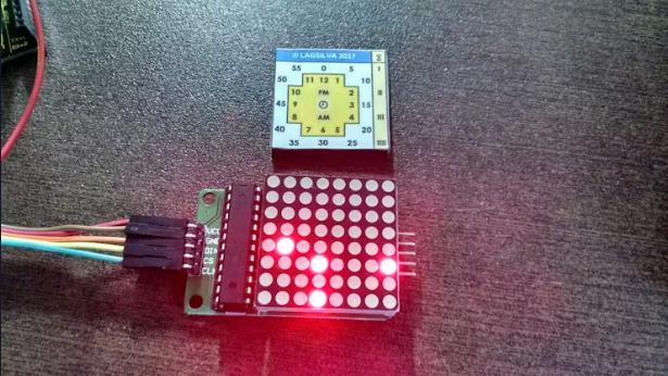
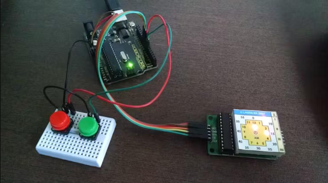
在这种情况下,我用它来模拟一个没有指针的模拟时钟,结果非常有趣。小时和分钟位于矩阵中心周围,给人一种熟悉的模拟时钟外观。我开发的代码应用了一些三角函数(正弦和余弦)来计算要显示在 LED 矩阵中的小时和分钟坐标。这样我节省了许多编码行。
组装非常简单,使用很少的组件,您处理它不会有任何问题。
让我们开始吧!
材料清单
您需要的材料如以下列表所示:
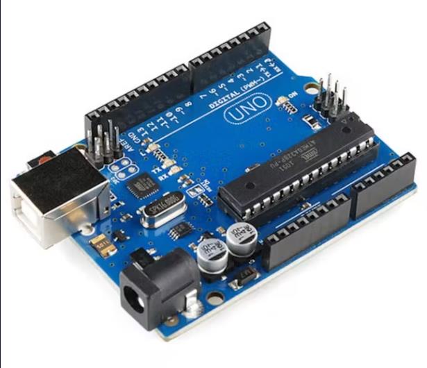
Arduino UNO R3
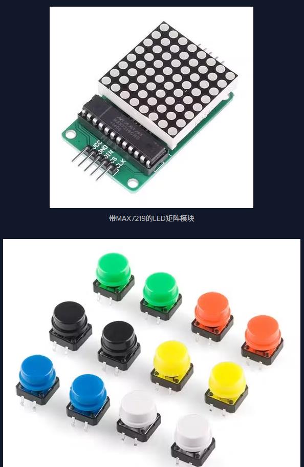
带MAX7219的LED矩阵模块(Maxim Integrated)
触觉按钮 (02 x)
面包板(小尺寸)
跳线
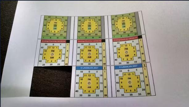
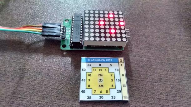
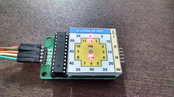
覆盖 LED 矩阵的纸质模板(打印见附件)
注意:此项目使用 Arduino 内部时钟。它不像外部 RTC(实时时钟)那么准确,但就本项目而言,它运行良好。
设置
启动后,显示的默认时间为 00:00 hs。
对于调整,只有两个触觉按钮来执行时间设置:
时间设置
会议记录的设置
只需按住它进行调整即可。
小时在显示屏上以 1 到 12 之间的数字显示。分钟以 0 到 55 之间的数字显示,以 5 分钟为步长。
在显示的最后一列中显示了从 1 到 4 的小数分钟,这些分钟必须添加到时钟主模板中显示的分钟中。
在显示屏中间,每秒有一个 LED 闪烁,还有两个用于 AM 和 PM 指示的 LED。

项目代码
/*
  Project:  Analog Clock with LED Matrix
  Author:   LAGSILVA
  Hardware: Arduino UNO R3 / LED Matrix with MAX72XX
  Date:     26.Jul.2017
  Revision: 1.1
  License:  CC BY-NC-ND 4.0
            (Attribution-NonCommercial-NoDerivatives 4.0 International)
*/

#include <LedControl.h>
#include <Time.h>
#include <TimeLib.h>

/*
  ***** Pin numbers for LedControl *****
  pin 10 is connected to the DataIn
  pin 08 is connected to the CLK
  pin 09 is connected to LOAD / CS
  We have only a single MAX72XX.
*/
LedControl lc = LedControl(10, 8, 9, 1);

byte xRef = 4; // Reference Row
byte yRef = 3; // Reference Collunm
byte mm1, mm5, hora, minuto;
byte ultMinuto = 10, ultHora = 10;
byte horaPin = 7, minutoPin = 6;
boolean ajustaHora = true, ajustaMinuto = true;
float pi = 3.1415927, xHH, yHH, xMM1, yMM1, xMM5, yMM5;


void setup() {

  pinMode(horaPin, INPUT_PULLUP);
  pinMode(minutoPin, INPUT_PULLUP);

  /* Wakeup call for MAX72XX */
  lc.shutdown(0, false);

  /* Set the brightness to a medium values */
  lc.setIntensity(0, 2);

}


void loop() {

  // Setup of Hours & Minutes
  ajustaHora = digitalRead(horaPin);
  ajustaMinuto = digitalRead(minutoPin);

  if (!ajustaHora) {
    adjustTime(3600);
  }

  if (!ajustaMinuto) {
    adjustTime(60);
  }

  hora = hour();
  minuto = minute();

  if (minuto != ultMinuto || hora != ultHora) {

    ultMinuto = minuto;
    ultHora = hora;
    lc.clearDisplay(0);

    // Minutes in steps of 5 (range of 0 to 55)
    mm5 = minuto / 5 * 5;

    //Minutes (1 to 4)
    mm1 = minuto % 5;

    // AM period
    if (hora >= 0 && hora <= 11) lc.setLed(0, xRef + 1, yRef, true);

    // PM period
    if (hora >= 12 && hora <= 23)lc.setLed(0, xRef - 1, yRef, true);

    // Coordinates for Hours & Minutes (steps of 5)
    xHH = round(-cos(hora * pi / 6) * 2) + xRef;
    yHH = round(sin(hora * pi / 6) * 2) + yRef;
    lc.setLed(0, xHH, yHH, true);

    xMM5 = round(-cos(mm5 * pi / 30) * 3.1) + xRef;
    yMM5 = round(sin(mm5 * pi / 30) * 3.1) + yRef;
    lc.setLed(0, xMM5, yMM5, true);

    //Coordinates for Minutes (1 to 4)
    yMM1 = yRef + 4;
    xMM1 = (mm1 - 1) * 2 + xRef - 3;
    if (mm1 > 0) lc.setLed(0, xMM1, yMM1, true);

  }

  // Center LED Blinking
  if (ajustaHora && ajustaMinuto) {
    lc.setLed(0, xRef, yRef, true);
    delay(200);
    lc.setLed(0, xRef, yRef, false);
    delay(800);
  }
  else delay(250);

}
【Arduino 动手做】带 LED 矩阵和 Arduino 的模拟时钟
项目链接:https://www.hackster.io/lagsilva/analog-clock-with-led-matrix-and-arduino-413467
项目作者:拉格西尔瓦
项目视频:https://www.youtube.com/watch?v=wMLpLXuzxwU
项目代码:https://www.hackster.io/code_files/513259/download
面板模版:https://hacksterio.s3.amazonaws.com/uploads/attachments/330868/analog_clock_-_templates_-_v1_1_HMaUwtHiUm.pdf


 他的勋章
他的勋章

评论