 返回首页
返回首页
 回到顶部
回到顶部
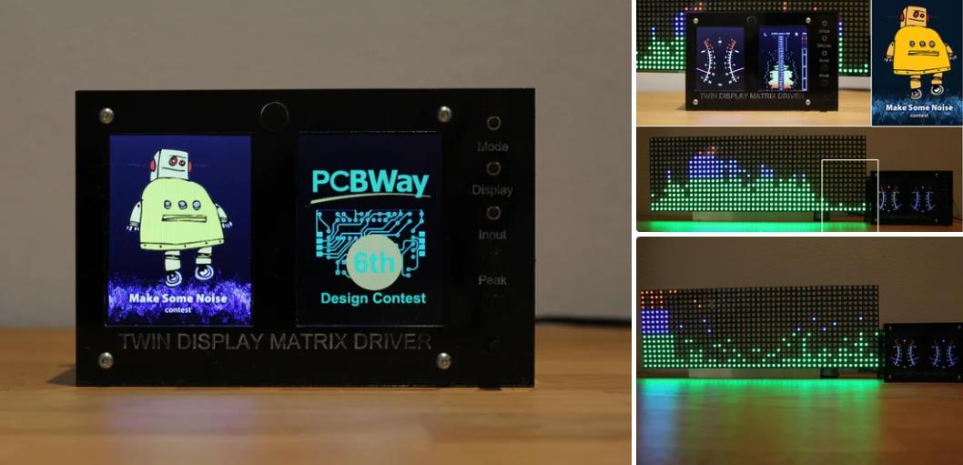
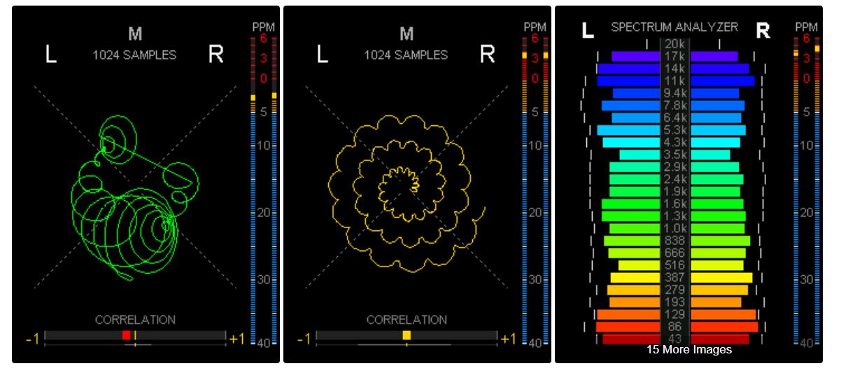
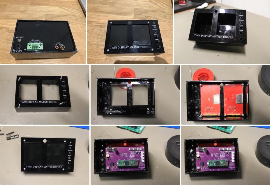
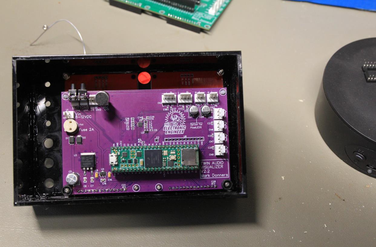
这个频谱分析仪项目简直令人惊叹。它包括一个 Teensy 微控制器板,可以同时以非常高的速度驱动 2 个显示器。凭借其板载音频芯片,它能够实时对音频进行频率分析,以创建 69 个通道的立体声频谱分析仪。
是的,你没看错我的意思!69 个立体声通道...所以这实际上是 138 个频率箱。最重要的是,我们将在第二个显示器上显示立体声 VU 表。所以或多或少我们实际上正在处理 140 个频道。
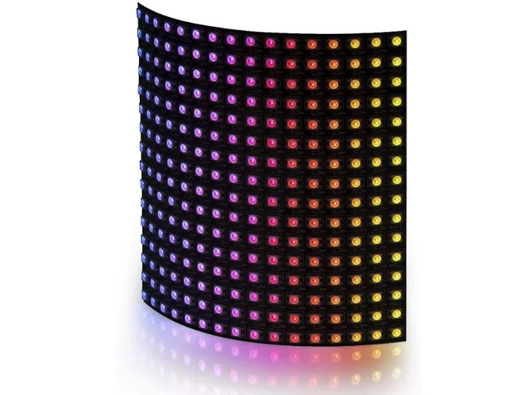
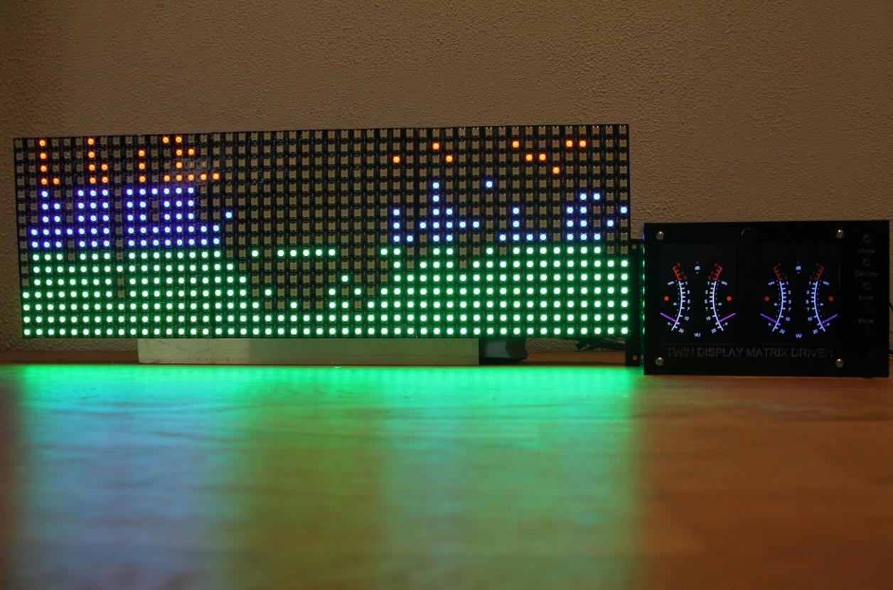
但还有更多:它可以同时驱动多达 3 个像素 LED 矩阵。因此,又增加了 768 个 LED
最重要的是:它是开源的!
你会需要:
带有所有组件的 PCB(购买预组装或仅购买 PCB 并添加您自己的组件)
但是在我的 tindy 商店里,您需要添加的只是显示器、保险丝和一个小控制器 4.1 : 在这里购买 PCB
使用 gerbers 来制造您自己的 PCB。我需要使用 PCBWAY.COM 您可以在此处下载所需的 gerber 文件: 下载 GERBER 文件
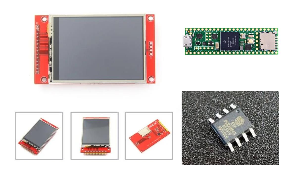
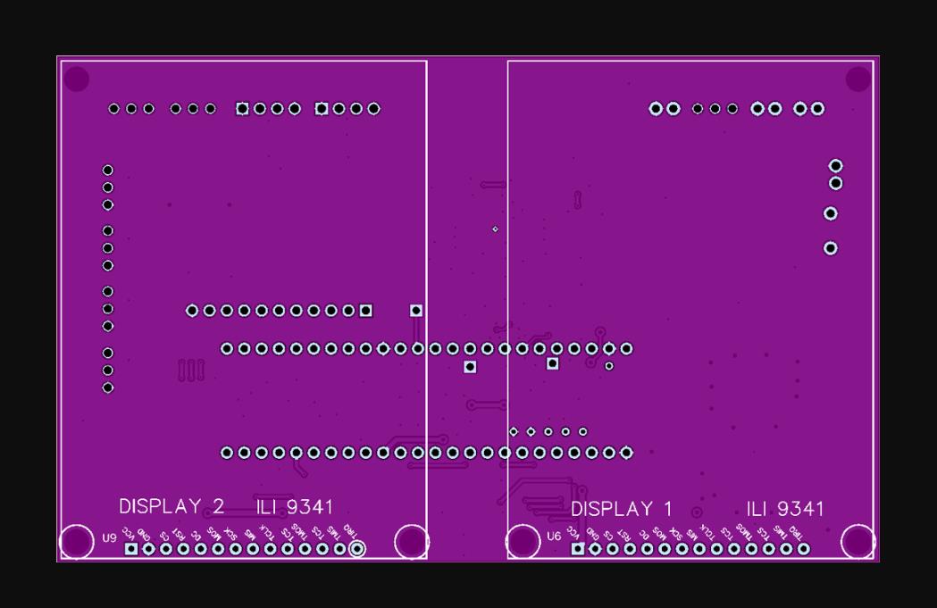
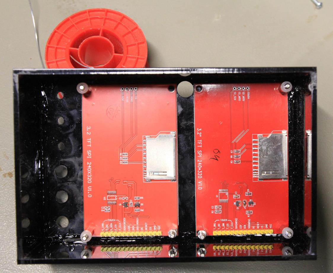
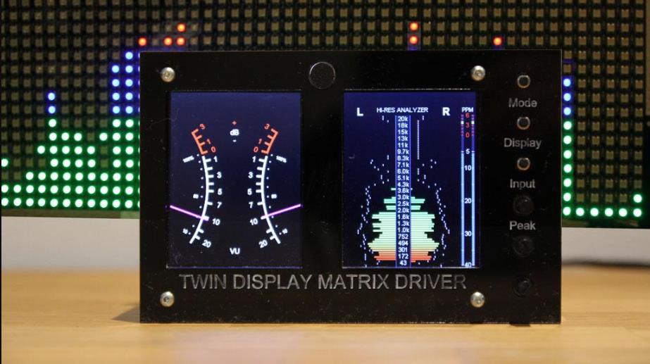
两个显示器类型:ILI9341这是 2.8 英寸版本。您也可以使用 3.2 英寸版本
Teensy 4.1 微控制器板
Teensy 的外部 Ram(您需要将其焊接到 teensy 板上)
如果您使用板载 PSU,请熔断 2AT TR5(您可以在 teensy 上使用 USB)
一些接头或连接器用于连接电线,或直接焊接到电路板上。
头
插座
如果您使用麦克风输入,则为一个驻极体麦克风
三个按钮进行作(如果您不使用像素化矩阵,则为两个)
三个 Potmeters,我使用 10K 版本(仅在添加像素化矩阵时才需要)
我们将使用两个显示器,每个显示器将使用一些屏幕缓冲区。由于缓冲区的大小相当大,由于我们需要的缓冲区数量众多,因此内部存储器是不够的。我们需要添加额外的内存。对我们来说,Teensy 4.1 有可能添加一个额外的内存芯片。
我在这里买了 Teensy 4.1:https://opencircuit.nl/product/teensy-4-1
您需要在预期的插座上添加 PSRAM,如图所示。
我用过这个芯片:8MB PSRAM64我在这里买的:https://opencircuit.nl/product/8-MB-PSRAM-chip-voor-Teensy-4.1
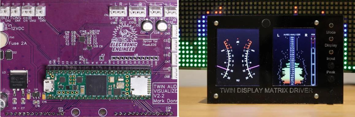
由于大多数组件直接连接到 PCB,因此所需电线的数量保持在最低限度
您可以查看原理图了解详细信息,但简而言之,归结为:
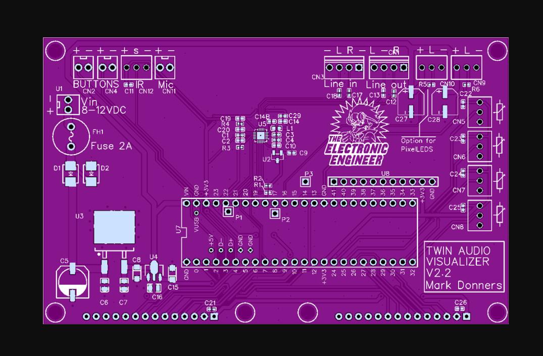
电波计(亮度、峰值延迟、输入增益)仅当您使用 LED 矩阵时才会转到连接器 CN5、CN6 和 CN10。将每个电位计的中心连接到连接器的中心引脚。将电位计的另外 2 个引脚连接到每个连接器的其余引脚。如果您的电位计反应是逆时针而不是 CW,反之亦然,只需转动该电位计的外侧两个引脚即可。
开关:
开关 1:CN2
开关 2:CN4
开关 3:标有 CN12 引脚(- 和 s)
麦克风连接到连接器 CN11
线路输入到连接器 CN3;两个外引脚接地,两个内引脚为通道 L 和 R
电源转到U1,注意板上的标记:+和-使用8-12VDC
Ledmatrix(我串联使用了 3 个矩阵,每个矩阵有 16 x 16 个 LED)连接器 CN10,查看 PCB 上的标记以查看 +、- 和 L(L = 数据线)
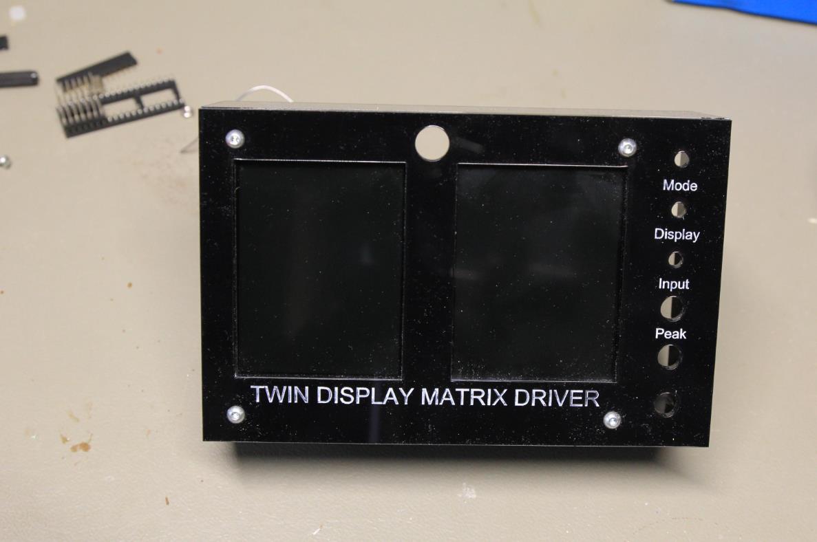
您不需要手册即可作本机。
这很简单。
使用麦克风或连接音频源。有一个按钮可以选择您正在使用的输入
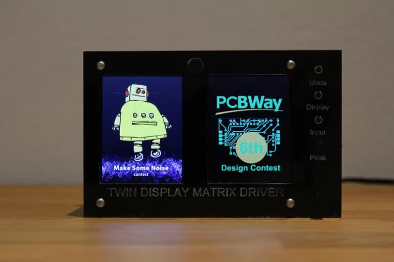
另一个按钮选择右侧显示屏上显示的屏幕
最后一个开关是选择像素化矩阵上显示的图案
还有 3 个锅计。( 10....50K 就可以完成这项工作 )
电波计1:LED显示强度
Potmeter 2:LED 显示增益
电波计 3:峰值延迟时间。(峰值下降到堆叠之前多长时间)


项目代码
#include <Adafruit_GFX.h>
#include <Adafruit_GrayOLED.h>
#include <Adafruit_SPITFT.h>
#include <Adafruit_SPITFT_Macros.h>
#include <gfxfont.h>

/**
       _    _____ ___   ___          _             _ _    __     ___                 _ _
      / \  |___  / _ \ / _ \        / \  _   _  __| (_) __\ \   / (_)___ _   _  __ _| (_)_______ _ __
     / _ \    / / | | | | | |_____ / _ \| | | |/ _` | |/ _ \ \ / /| / __| | | |/ _` | | |_  / _ \ '__|
    / ___ \  / /| |_| | |_| |_____/ ___ \ |_| | (_| | | (_) \ V / | \__ \ |_| | (_| | | |/ /  __/ |Twin
   /_/   \_\/_/  \___/ \___/     /_/   \_\__,_|\__,_|_|\___/ \_/  |_|___/\__,_|\__,_|_|_/___\___|_|Display
   with optional added Neopixel matrix

   ReVox A700 AudioVisualizer
   Copyright (C) 2021 by DIYLAB <https://www.diylab.de> GitHub: <https://github.com/DIYLAB-DE/AudioVisualizer>
   Modification for Dual Display and pixelleds done by Mark Donners, TheElectronicEngineer.nl
   ~~~~~~~~~~~~~~~~~~~~~~~~~~~~~~~~~~~~~~~~~~~~~~~~~~~~~~~~~~~~~~~~~~~~~~~~~~~~~~~~~~~~~~~~~~~~~~~~
   This Software is free software: you can redistribute it and/or modify it under the terms of the
   GNU General Public License as published by the Free Software Foundation, either version 3 of the
   License, or (at your option) any later version.

   This Software is distributed in the hope that it will be useful, but WITHOUT ANY WARRANTY;
   without even the implied warranty of MERCHANTABILITY or FITNESS FOR A PARTICULAR PURPOSE.
   See the GNU General Public License for more details: <http://www.gnu.org/licenses/>

   ~~~~~~~~~~~~~~~~~~~~~~~~~~~~~~~~~~~~~~~~~~~~~~~~~~~~~~~~~~~~~~~~~~~~~~~~~~~~~~~~~~~~~~~~~~~~~~~~
   !!! IMPORTANT !!!
   The GNU General Public License (GNU GPL) obligates the user to also place the software under the
   conditions of the GPL (copyleft) when redistributing the software in its original or modified form
   (so-called derivative works). If the licensee does not comply with the conditions, the right to free use expires retroactively!
   Therefore, the user is also required to make the source code available and to subject the derived software to the GPL.
   ~~~~~~~~~~~~~~~~~~~~~~~~~~~~~~~~~~~~~~~~~~~~~~~~~~~~~~~~~~~~~~~~~~~~~~~~~~~~~~~~~~~~~~~~~~~~~~~~
   !!! WICHTIG !!!
   Die GNU General Public License (GNU GPL) verpflichtet den Nutzer dazu, bei Weiterverbreitung der Software
   in ihrer ursprünglichen oder veränderten Form (sog. abgeleitete Werke), diese ebenfalls unter die Bedingungen der GPL zu stellen (Copyleft).
   Hält sich der Lizenznehmer nicht an die Bedingungen, erlischt die Befugnis zur freien Benutzung rückwirkend!
   Daher ist der Verwender gehalten, ebenfalls den Quellcode zugänglich zu machen und die abgeleitete Software wiederum der GPL zu unterwerfen.
   ~~~~~~~~~~~~~~~~~~~~~~~~~~~~~~~~~~~~~~~~~~~~~~~~~~~~~~~~~~~~~~~~~~~~~~~~~~~~~~~~~~~~~~~~~~~~~~~~

   Special thanks to Bodmer <https://github.com/Bodmer> for the AA drawing routines and the rainbow colors!

   Used libraries
   ---------------
   Optimized ILI9341 screen driver library for Teensy 4/4.1, with vsync and differential updates: <https://github.com/vindar/ILI9341_T4>
   TGX - a tiny/teensy graphics library: <https://github.com/vindar/tgx>
   Arduino OneButton Library: <https://github.com/mathertel/OneButton> (install via the Arduino library manager)
   IRremote Arduino Library: <https://github.com/Arduino-IRremote/Arduino-IRremote>
   TeensyID: https://github.com/sstaub/TeensyID

   Used development software
   -------------------------
   Arduino IDE 1.8.19
   Teensyduino, Version 1.56


/**************************************************************************************************
   Updated to version for 2 displays. The function of the first display is unchanged, compared to
   the orignal firmware. the second display will always show Stereo Analog VU meter
   Also implemented extra button to switch between line and mic input

   Take Note: For this sketch to work, you will need Arduino 4.1 with added EXTERNAL PSRAM

   This update will include Pixelled matrix and potmeters to adjust sensitivity
   Compared to the original version 2.0.1, the folowing files where changed:
   AudioVisualizer, Analog, Gfx
   Logo.h, was added

   I did a succesful compilation using the following library versions:
   Using library Wire at version 1.0
   Using library Audio at version 1.3
   Using library SPI at version 1.0
   Using library SD at version 2.0.0
   Using library SdFat at version 2.1.0
   Using library SerialFlash at version 0.5
   Using library ILI9341_T4-main at version 0.1
   Using library tgx-main at version 0.5
   Using library EEPROM at version 2.0
   Using library OneButton at version 2.0.4
   Using library IRremote at version 3.6.1
   Using library TeensyID-main at version 1.3.3
   Using library ILI9488_t3 at version 1.0


 *************************************************************************************************/

//////////////////////////////////////////////////////////////////////////////////////////////////
// USER CONFIG SECTION (please only edit here!)                                                 //
//////////////////////////////////////////////////////////////////////////////////////////////////

#define VERSION "v4.0, 25.10.2023"
#define SHOWLOGO                true  // show logo
#define BUTTON                     2  // PIN0
#define BUTTON2                    3  // ADDED By MARK DONNERS
//#define IR                         4  // PIN4
#define BUTTON3                    4  // Pin xx Added By Mark Donners

// set the pins: here for SPI0 on Teensy 4.x
// ***  Recall that DC must be on a valid cs pin !!! ***

// FIRST SCREEN IS WIRED TO SPI0
#define PIN_SCK0        13  // mandatory
#define PIN_MISO0       12  // mandatory
#define PIN_MOSI0       11  // mandatory
#define PIN_DC0         10  // mandatory
#define PIN_CS0          9  // mandatory (but can be any digital pin)
#define PIN_RESET0       6  // could be omitted (set to 255) yet it is better to use (any) digital pin whenever possible.
#define PIN_BACKLIGHT0 5  // optional. Set this only if the screen LED pin is connected directly to the Teensy
#define PIN_TOUCH_IRQ0 255  // optional. Set this only if touch is connected on the same spi bus (otherwise, set it to 255)
#define PIN_TOUCH_CS0  255  // optional. Set this only if touch is connected on the same spi bus (otherwise, set it to 255)

// ADDED By MARK DONNERS
// SECOND SCREEN IS WIRED TO SPI1
#define PIN_SCK1        27  // mandatory
#define PIN_MISO1        1  // mandatory
#define PIN_MOSI1       26  // mandatory
#define PIN_DC1          0  // mandatory
#define PIN_CS1         30  // mandatory (but can be any digital pin)
#define PIN_RESET1      29  // could be omitted (set to 255) yet it is better to use (any) digital pin whenever possible.
#define PIN_BACKLIGHT1 28  // optional. Set this only if the screen LED pin is connected directly to the Teensy
#define PIN_TOUCH_IRQ1 255  // optional. Set this only if touch is connected on the same spi bus (otherwise, set it to 255)
#define PIN_TOUCH_CS1  255  // optional. Set this only if touch is connected on the same spi bus (otherwise, set it to 255)
// Changed the default SPI speed
#define SPI_SPEED          50000000  // SPI speed
#define SPI_SPEED2         50000000  // SPI speed
//////////////////////////////////////////////////////////////////////////////////////////////////
/**/
#include <Wire.h>
#include <Audio.h>
#include "SPI.h"
#include "ILI9341Driver.h"
#include <ILI9341_T4.h>
#include <tgx.h>
#include <EEPROM.h>
#include <OneButton.h>
//IR#include <IRremote.h>
#include <TeensyID.h>
#include <Adafruit_NeoMatrix.h>                    // Fastled Neomatrix driver.
#include <Adafruit_NeoPixel.h>
#include "_timers.h"
#include "globals.h"
#include "Pixel_Spec.h"
#include "helpers.h"
#include "graphics.h"
#include "_ili9341_t3n_font_Arial.h"
#include "_ili9341_t3n_font_ArialBold.h"

//////////////////////////////////////////////////////////////////////////////////////////////////

/// <summary>
/// inherit from the 'AudioControlSGTL5000' class to modify the CHIP_ANA_ADC_CTRL register
/// </summary>
#include "control_sgtl5000.h"
class mSGTL5000 : public AudioControlSGTL5000 {
  public:
    void attGAIN(uint8_t att) {
      modify(0x0020, (att & 1) << 8, 1 << 8);
    }
};

// namespace for draw graphics primitives
using namespace tgx;

// Framebuffers and some variables below have moved to External memory, compared to orginal firmware
// all related to the use of two displays
// framebuffers
DMAMEM uint16_t internalBuffer[240 * 320] = { 0 }; // used for internal buffering
DMAMEM  uint16_t internalBuffer1[240 * 320] = { 0 }; // used for internal buffering
EXTMEM  uint16_t frontBuffer[240 * 320] = { 0 };    // paint in this buffer
EXTMEM  uint16_t frontBuffer1[240 * 320] = { 0 };     // background buffer
EXTMEM uint16_t backBuffer[240 * 320] = { 0 };     // background buffer
EXTMEM uint16_t backBuffer1[240 * 320] = { 0 };     // background buffer

/********************************************************************************************************************************
  * ** // Adafruit_NeoMaxtrix                                                                         **
  ********************************************************************************************************************************/
Adafruit_NeoMatrix matrix = Adafruit_NeoMatrix(kMatrixWidth, kMatrixHeight, LED_PIN,
  NEO_MATRIX_BOTTOM     + NEO_MATRIX_RIGHT +
  NEO_MATRIX_COLUMNS + NEO_MATRIX_ZIGZAG,
  NEO_GRB            + NEO_KHZ800);

const uint16_t colors[] = {
  matrix.Color(255, 0, 0), matrix.Color(0, 255, 0), matrix.Color(0, 0, 255) };


// samplebuffers
int16_t samplesLeft[2048] = { 0 };
int16_t samplesRight[2048] = { 0 };

// screen driver objects
ILI9341_T4::ILI9341Driver tft(PIN_CS0, PIN_DC0, PIN_SCK0, PIN_MOSI0, PIN_MISO0, PIN_RESET0, PIN_TOUCH_CS0, PIN_TOUCH_IRQ0); // for screen on SPI0
ILI9341_T4::ILI9341Driver tft1(PIN_CS1, PIN_DC1, PIN_SCK1, PIN_MOSI1, PIN_MISO1, PIN_RESET1, PIN_TOUCH_CS1, PIN_TOUCH_IRQ1); // for screen on SPI1

// two diff buffers
ILI9341_T4::DiffBuffStatic<8000> diff1;
ILI9341_T4::DiffBuffStatic<8000> diff2;

// two diff buffers for second display
ILI9341_T4::DiffBuffStatic<8000> diff3;
ILI9341_T4::DiffBuffStatic<8000> diff4;

// images that encapsulates framebuffers
Image<RGB565> im(frontBuffer, 240, 320);
Image<RGB565> im1(frontBuffer1, 240, 320);
EXTMEM Image<RGB565> bg(backBuffer, 240, 320);
EXTMEM Image<RGB565> bg1(backBuffer1, 240, 320);

// instantiate button object
OneButton btn(BUTTON, true, true);
OneButton btn2(BUTTON2, true, true);
OneButton btn3(BUTTON3, true, true);
// GUItool: begin automatically generated code
AudioInputI2S            i2s1;           //xy=205,270
AudioOutputI2S           i2s2;           //xy=233.00000381469727,400.0000057220459
AudioAnalyzeFFT1024      fft1024_1;      //xy=425.00000762939453,132.00000190734863
AudioAnalyzeFFT1024      fft1024_2;      //xy=426.00000381469727,320.0000047683716
AudioAnalyzeRMS          rms1;           //xy=431.00000381469727,93.00000190734863
AudioRecordQueue         queue2;         //xy=431.00000381469727,280.00000381469727
AudioAnalyzePeak         peak1;          //xy=432.00000762939453,54.000003814697266
AudioRecordQueue         queue1;         //xy=432.00000381469727,171.00000381469727
AudioMixer4              mixer1;         //xy=432.00000381469727,225.00000381469727
AudioAnalyzeRMS          rms2;           //xy=433.00000762939453,359.0000047683716
AudioAnalyzePeak         peak2;          //xy=435.00000762939453,399.0000057220459
AudioAnalyzeFFT1024      fft1024_3;      //xy=566.0000076293945,225.00000286102295
AudioConnection          patchCord1(i2s1, 0, queue1, 0);
AudioConnection          patchCord2(i2s1, 0, peak1, 0);
AudioConnection          patchCord3(i2s1, 0, rms1, 0);
AudioConnection          patchCord4(i2s1, 0, fft1024_1, 0);
AudioConnection          patchCord5(i2s1, 0, mixer1, 0);
AudioConnection          patchCord6(i2s1, 0, i2s2, 0);
AudioConnection          patchCord7(i2s1, 1, queue2, 0);
AudioConnection          patchCord8(i2s1, 1, fft1024_2, 0);
AudioConnection          patchCord9(i2s1, 1, rms2, 0);
AudioConnection          patchCord10(i2s1, 1, peak2, 0);
AudioConnection          patchCord11(i2s1, 1, mixer1, 1);
AudioConnection          patchCord12(i2s1, 1, i2s2, 1);
AudioConnection          patchCord13(mixer1, fft1024_3);
mSGTL5000                sgtl5000_1;
// GUItool: end automatically generated code

/// <summary>
/// setup
/// </summary>
void setup() {
  Serial.println("enter setup");
  //  The following code was added by Mark Donners to change the internal busspeed for the external Memory
  // turn on clock  (TODO: increase clock speed later, slow & cautious for first release)
  CCM_CCGR7 |= CCM_CCGR7_FLEXSPI2(CCM_CCGR_OFF);
  CCM_CBCMR = (CCM_CBCMR & ~(CCM_CBCMR_FLEXSPI2_PODF_MASK | CCM_CBCMR_FLEXSPI2_CLK_SEL_MASK))
              | CCM_CBCMR_FLEXSPI2_PODF(4) | CCM_CBCMR_FLEXSPI2_CLK_SEL(2);
  CCM_CCGR7 |= CCM_CCGR7_FLEXSPI2(CCM_CCGR_ON);

  // link the button events
  btn.attachClick(buttonClick);
  btn.attachDoubleClick(buttonDoubleClick);
  btn.attachLongPressStart(buttonLongPressStart);
  btn.attachLongPressStop(buttonLongPressStop);
  btn.attachDuringLongPress(buttonLongPress);

  // Added functions for button2 by Mark Donners
  btn2.attachClick(button2Click);
  // added function for button 3 ( mode );
  btn3.attachClick(button3Click);


  // set bin ranges
  setBins();

  // Audio
  AudioMemory(128);//64

  sgtl5000_1.enable();
  InputSelect=!InputSelect; // we need to invert it once because it will change back in the button2Click function
  button2Click(); //this will call the subroutine where I change the input selector.
  // some default settings for the sgtl5000_1 where moved to the button2Click function

  // dsp
  sgtl5000_1.autoVolumeDisable();
  sgtl5000_1.surroundSoundDisable();
  sgtl5000_1.enhanceBassDisable();

  // fft
  fft1024_1.windowFunction(AudioWindowHanning1024);
  fft1024_2.windowFunction(AudioWindowHanning1024);
  fft1024_3.windowFunction(AudioWindowHanning1024);

  // display
  while (!tft.begin(SPI_SPEED)) delay(1000);

  tft.setScroll(0);
  tft.setFramebuffers(internalBuffer); // set 1 internal framebuffer -> activate float buffering
  tft.setDiffBuffers(&diff1, &diff2);  // set the 2 diff buffers => activate differential updates
  tft.setDiffGap(16);                   // use a small gap for the diff buffers
  tft.setRefreshRate(120);             // around 120hz for the display refresh rate
  tft.setVSyncSpacing(2);              // set framerate = refreshrate/2 (and enable vsync at the same time)

  // ADDED by Mark Donners for Second Display
  while (!tft1.begin(SPI_SPEED2)) delay(1000);
  tft1.setScroll(0);
  tft1.setFramebuffers(internalBuffer1); // set 1 internal framebuffer -> activate float buffering
  tft1.setDiffBuffers(&diff3, &diff4);  // set the 2 diff buffers => activate differential updates
  tft1.setDiffGap(16);                   // use a small gap for the diff buffers
  tft1.setRefreshRate(120);             // around 120hz for the display refresh rate
  tft1.setVSyncSpacing(2);              // set framerate = refreshrate/2 (and enable vsync at the same time)

  // make sure backlight is on
  if (PIN_BACKLIGHT0 != 255) {
    pinMode(PIN_BACKLIGHT0, OUTPUT);
    digitalWrite(PIN_BACKLIGHT0, HIGH);
  }
  // ADDED by Mark Donners for Second Display
  // make sure backlight is on
  if (PIN_BACKLIGHT1 != 255) {
    pinMode(PIN_BACKLIGHT1, OUTPUT);
    digitalWrite(PIN_BACKLIGHT1, HIGH);
  }

  // force reset to factory defaults
  if (digitalRead(BUTTON) == LOW) {
    clearEEPROM();
    // waiting for release the button
    while (digitalRead(BUTTON) == LOW) {}
  }

  // get config from EEPROM or initialize EEPROM
  if (isFirstStart()) {
    clearEEPROM();
    delay(3000);
  } else {
    readGLOBALConfig();
    readDBCorrection();
    readDIGITALConfig();
    readANALOGConfig();
    readFFTConfig();
    readGONIOConfig();
    readREMOTECONTROLConfig();
  }

  // show logo
#if SHOWLOGO
  showLogo();
#endif

  // initialize display from ModuleType
  initalizeDisplayFromModuleType(moduleType);

matrix.begin();
matrix.setTextColor(colors[0]);

}


int x    = matrix.width();
int pass = 0;

/// <summary>
/// mainloop
/// </summary>
void loop() {
  static elapsedMillis fps = 0;
  //oddeven=!oddeven;
  // watching the button
  btn.tick();
  // watching the button2
  btn2.tick();
  btn3.tick();
  // watching the serialport

  // draw modules
  if (!lockScreenUpdate && !DIGITAL_MenuActive && !ANALOG_MenuActive && !FFT_MenuActive && !GONIO_MenuActive) {
    drawAnalog2(false);

    if (moduleType == 0) drawDigital(false);
    else if (moduleType == 1) drawAnalog(false);
    else if (moduleType == 2) drawFFT(false);
    else if (moduleType == 3) drawGonio(false);

    // send global RMS & PPM data
    if (calibrate && fps > 16) {
      fps = 0;
      sendRMSPPM();
    }
  }

////*******************++
//matrix.clear();
int SENSE = analogRead(SENSEPOT)/2;
Peakdelay= map(analogRead(PEAKDELAYPOT),0,1024,0,100); // this is the peak delay pot

 for(int i=0; i<numBands; i++) {
 FreqBinsNew[i]=(fft1024_3.read(Startbin,Stopbin) * SENSE);
  }


// Process the  data from bandValues and transform them into bar heights
  for (byte band = 0; band < numBands; band++)
  { // Scale the bars for the display
    int barHeight = FreqBinsNew[band];
    if (barHeight > TOP) barHeight = TOP;
    // Small amount of averaging between frames
    barHeight = ((FreqBinsOld[band] * 1) + barHeight) / 2; // Fast Filter, more rapid movement
    // barHeight = ((oldBarHeights[band] * 2) + barHeight) / 3; // minimum filter makes changes more smooth

    // Move peak up

    if (barHeight > peak[band])
    {
      peak[band] = min(TOP, barHeight);
      PeakFlag[band] = 1;
    }

    /*
       Mode 0: All leds OFF
       Mode 1: TriBar each Column is devided into 3 sections, Bottom,Middle and Top, Each section has different color
       Mode 2: Tribar without peaks
       Mode 3: No bars, only peaks in try color
       Mode 4: yellow bars white peaks
       Mode 5: yellow bars no peaks
       Mode 6: Center Bars yellow with red outerline
       Mode 7: Center Bars green with purple outerline

    */


    // Now visualize those bar heights
    switch (LedMode) {
      case 0:
      NoBars(band, barHeight);
      break;

      case 1:
      TriBar(band, barHeight);
      TriPeak(band);
      break;


      case 2:
      TriBar(band, barHeight);
      break;

      case 3:
      NoBars(band, barHeight);
      TriPeak(band);
      break;


      case 4:
      YellowBars(band, barHeight);
      NormalPeak(band,50,78,90);
      break;

      case 5:
      YellowBars(band, barHeight);
      break;

      case 6:
      centerBars(band, barHeight);
      break;

      case 7:
      centerBars2(band, barHeight);
      break;

    }
    FreqBinsOld[band] = barHeight;  // Save oldBarHeights for averaging later
  }


BRIGHTNEW=map(analogRead(BRIGHTPOT),0,1023,10,200);

 matrix.setBrightness(BRIGHTNEW);
  matrix.show();


EVERY_N_MILLISECONDS(Fallingspeed) {
    for (byte band = 0; band < numBands; band++) {
      if (PeakFlag[band] == 1) {
        PeakTimer[band]++;
        if (PeakTimer[band] > Peakdelay) {
          PeakTimer[band] = 0;
          PeakFlag[band] = 0;
        }
      } else if (peak[band] > 0) {
        peak[band] -= 1;
      }
    }

  }


}

/// <summary>
/// samples = sampleblocks * 128
/// </summary>
void setSampleBlocks() {
  lockScreenUpdate = true;
  queue1.freeBuffer();
  queue2.freeBuffer();
  memset(samplesLeft, 0, sizeof(samplesLeft));
  memset(samplesRight, 0, sizeof(samplesRight));
  GONIO_SampleBlocks = 8;
  if (GONIO_Samples == 1) GONIO_SampleBlocks = 16;
  lockScreenUpdate = false;
}

/// <summary>
/// get samples for left and right channel
/// </summary>
/// <param name="blocks"></param>
void getSamples(uint16_t blocks) {
  if (blocks == 0) {
    queue1.readBuffer();
    queue1.freeBuffer();
    queue2.readBuffer();
    queue2.freeBuffer();
  } else {
    if (queue1.available() >= blocks && queue2.available() >= blocks) {
      for (byte i = 0; i < blocks; i++) {
        memcpy(&samplesLeft[i * 128], queue1.readBuffer(), 256);
        memcpy(&samplesRight[i * 128], queue2.readBuffer(), 256);
        queue1.freeBuffer();
        queue2.freeBuffer();
      }
    }
  }
}

/// <summary>
/// this function will be called when the button was pressed 1 time
/// </summary>
void buttonClick() {
  if (++moduleType > 3) moduleType = 0;
  modeSwitch();
}

/// this function will be called when the button2 was pressed 1 time
/// ADDED By Mark Donners
/// </summary>
void button2Click() {


  if (InputSelect == AUDIO_INPUT_LINEIN) {
    // change parameters for optimal use with your mic
    InputSelect = AUDIO_INPUT_MIC;
    sgtl5000_1.inputSelect(InputSelect);
    sgtl5000_1.lineOutLevel(13); // 3.16 Volts p-p
    sgtl5000_1.volume(0.7f);     // 0.8 corresponds to the maximum undistorted output for a full scale signal
    sgtl5000_1.lineInLevel(0);   // 3.12 Volts p-p
    sgtl5000_1.attGAIN(0);       // ADC volume range reduction down by 6.0 dB
    Serial.println("Input change to Microphone");
  }

  else {
    // change parameters for optimal use with your line in
    InputSelect = AUDIO_INPUT_LINEIN;
    sgtl5000_1.inputSelect(InputSelect);
    sgtl5000_1.lineOutLevel(13); // 3.16 Volts p-p
    sgtl5000_1.volume(0.7f);     // 0.8 corresponds to the maximum undistorted output for a full scale signal
    sgtl5000_1.lineInLevel(0);   // 3.12 Volts p-p
    sgtl5000_1.attGAIN(0);       // ADC volume range reduction down by 6.0 dB
    Serial.println("Input change to Line-IN");
  }


}
void button3Click() {
  Serial.println("Mode button was pressed");
  LedMode++;
  if (LedMode>LedModeMax)LedMode=0;
  Serial.println(LedMode);
}
/// <summary>
/// this function will be called when the button was pressed 2 times in a int16_t timeframe
/// </summary>
void buttonDoubleClick() {
  setSubMode(moduleType);
}

/// <summary>
/// this function will be called often, while the button is pressed for a long time
/// </summary>
void buttonLongPress() {
}

/// <summary>
/// this function will be called once, when the button is pressed for a long time
/// </summary>
void buttonLongPressStart() {
  calibrate = !calibrate;
  initalizeDisplayFromModuleType(moduleType);
}

/// <summary>
/// this function will be called once, when the button is released after beeing pressed for a long time
/// </summary>
void buttonLongPressStop() {
}

/// <summary>
/// switch module
/// </summary>
void modeSwitch() {
  lockScreenUpdate = true;
  EEPROM.put(20, moduleType);
  initalizeDisplayFromModuleType(moduleType);
  Serial.printf("{ModuleType=%i}", moduleType);
  lockScreenUpdate = false;
}

/// <summary>
/// initialize display from ModuleType
/// </summary>
/// <param name="mType"></param>
void initalizeDisplayFromModuleType(int16_t mType) {
  if (mType < 0 || mType > 3) {
    mType = 0;
    moduleType = 0;
  }

  lockScreenUpdate = true;
  if (mType == 0) displayInitDigital(true);
  if (mType == 1) displayInitAnalog();
  if (mType == 2) displayInitFFT(true);
  if (mType == 3) displayInitGonio(true);
  display2InitAnalog(); // second display always vu meter

  lockScreenUpdate = false;


}

/// <summary>
/// set subMode
/// </summary>
void setSubMode(int16_t mType) {
  lockScreenUpdate = true;
  switch (mType) {
    case 0: // digitalmeter
      if (++DIGITAL_WorkMode > 3)  DIGITAL_WorkMode = 0;
      EEPROM.put(504, DIGITAL_WorkMode);
      setMode(true);
      break;
    case 1:
      break;
    case 2: // spectrumanalyzer
      if (++FFT_WorkMode > 11) FFT_WorkMode = 0;
      EEPROM.put(706, FFT_WorkMode);
      setMode(true);
      break;
    case 3: // goniometer
      if (++GONIO_WorkMode > 7) GONIO_WorkMode = 0;
      EEPROM.put(806, GONIO_WorkMode);
      setMode(true);
      break;
  }
  lockScreenUpdate = false;
}

/// <summary>
/// set mode
/// </summary>
void setMode(bool showMessage) {
  switch (moduleType) {
    case 0: // digitalmeter
      switch (DIGITAL_WorkMode) {
        case 0:
          DIGITAL_dBLow = -40;
          DIGITAL_PeakHold = false;
          if (showMessage) messageBox("-40dB");
          break;
        case 1:
          DIGITAL_dBLow = -30;
          DIGITAL_PeakHold = false;
          if (showMessage) messageBox("-30dB");
          break;
        case 2:
          DIGITAL_dBLow = -40;
          DIGITAL_PeakHold = true;
          if (showMessage) messageBox("-40dB HOLD");
          break;
        case 3:
          DIGITAL_dBLow = -30;
          DIGITAL_PeakHold = true;
          if (showMessage) messageBox("-30dB HOLD");
          break;
      }
      break;

    case 1: // analogmeter
      break;

    case 2: // spectrumanalyzer
      switch (FFT_WorkMode) {
        case 0:
          FFT_dBLow = -40;
          FFT_LevelBarMode = 1 /*RMS*/;
          FFT_PeakHold = false;
          if (showMessage) messageBox("RMS -40dB");
          break;
        case 1:
          FFT_dBLow = -40;
          FFT_LevelBarMode = 0 /*PEAK*/;
          FFT_PeakHold = false;
          if (showMessage) messageBox("PPM -40dB");
          break;
        /*****************************************/
        case 2:
          FFT_dBLow = -30;
          FFT_LevelBarMode = 1 /*RMS*/;
          FFT_PeakHold = false;
          if (showMessage) messageBox("RMS -30dB");
          break;
        case 3:
          FFT_dBLow = -30;
          FFT_LevelBarMode = 0 /*PEAK*/;
          FFT_PeakHold = false;
          if (showMessage) messageBox("PPM -30dB");
          break;
        /*****************************************/
        case 4:
          FFT_dBLow = -40;
          FFT_LevelBarMode = 1 /*RMS*/;
          FFT_PeakHold = true;
          if (showMessage) messageBox("RMS.HOLD -40dB");
          break;
        case 5:
          FFT_dBLow = -40;
          FFT_LevelBarMode = 0 /*PEAK*/;
          FFT_PeakHold = true;
          if (showMessage) messageBox("P.HOLD -40dB");
          break;
        /*****************************************/
        case 6:
          FFT_dBLow = -30;
          FFT_LevelBarMode = 1 /*RMS*/;
          FFT_PeakHold = true;
          if (showMessage) messageBox("RMS.HOLD -30dB");
          break;
        case 7:
          FFT_dBLow = -30;
          FFT_LevelBarMode = 0 /*PEAK*/;
          FFT_PeakHold = true;
          if (showMessage) messageBox("P.HOLD -30dB");
          break;
        /*****************************************/
        case 8:
          FFT_dBLow = -40;
          FFT_LevelBarMode = 1 /*RMS*/;
          FFT_PeakHold = true;
          if (showMessage) messageBox("RMS.HOLD4 -40dB");
          break;
        case 9:
          FFT_dBLow = -40;
          FFT_LevelBarMode = 0 /*PEAK*/;
          FFT_PeakHold = true;
          if (showMessage) messageBox("P.HOLD4 -40dB");
          break;
        /*****************************************/
        case 10:
          FFT_dBLow = -30;
          FFT_LevelBarMode = 1 /*RMS*/;
          FFT_PeakHold = true;
          if (showMessage) messageBox("RMS.HOLD4 -30dB");
          break;
        case 11:
          FFT_dBLow = -30;
          FFT_LevelBarMode = 0 /*PEAK*/;
          FFT_PeakHold = true;
          if (showMessage) messageBox("P.HOLD4 -30dB");
          break;
      }
      break;

    case 3: // goniometer
      switch (GONIO_WorkMode) {
        case 0:
          GONIO_dBLow = -40;
          GONIO_BarMode = 1 /*RMS*/;
          GONIO_PeakHold = false;
          if (showMessage) messageBox("RMS -40dB");
          break;
        case 1:
          GONIO_dBLow = -40;
          GONIO_BarMode = 0 /*PEAK*/;
          GONIO_PeakHold = false;
          if (showMessage) messageBox("PPM -40dB");
          break;
        case 2:
          GONIO_dBLow = -30;
          GONIO_BarMode = 1 /*RMS*/;
          GONIO_PeakHold = false;
          if (showMessage) messageBox("RMS -30dB");
          break;
        case 3:
          GONIO_dBLow = -30;
          GONIO_BarMode = 0 /*PEAK*/;
          GONIO_PeakHold = false;
          if (showMessage) messageBox("PPM -30dB");
          break;
        case 4:
          GONIO_dBLow = -40;
          GONIO_BarMode = 1 /*RMS*/;
          GONIO_PeakHold = true;
          if (showMessage) messageBox("RMS.HOLD -40dB");
          break;
        case 5:
          GONIO_dBLow = -40;
          GONIO_BarMode = 0 /*PEAK*/;
          GONIO_PeakHold = true;
          if (showMessage) messageBox("P.HOLD -40dB");
          break;
        case 6:
          GONIO_dBLow = -30;
          GONIO_BarMode = 1 /*RMS*/;
          GONIO_PeakHold = true;
          if (showMessage) messageBox("RMS.HOLD -30dB");
          break;
        case 7:
          GONIO_dBLow = -30;
          GONIO_BarMode = 0 /*PEAK*/;
          GONIO_PeakHold = true;
          if (showMessage) messageBox("P.HOLD -30dB");
          break;
      }
      break;
  }
}

/// <summary>
/// start queue
/// </summary>
void queueStart() {
  queue1.clear();
  queue2.clear();
  queue1.begin();
  queue2.begin();
}

/// <summary>
/// stop queue
/// </summary>
void queueStop() {
  queue1.end();
  queue2.end();
  queue1.clear();
  queue2.clear();
  queue1.freeBuffer();
  queue2.freeBuffer();
}

void TriBar(int band, int barHeight) {
  int x =  band;
// first draw active pixels
    for (int y = TOP; y >= TOP - barHeight; y--) {
      if (y < 4) matrix.drawPixel(x, y, matrix.Color(70,0,0));     //Top red
      else if (y > 8) matrix.drawPixel(x, y, matrix.Color(0,70,0)); //red
      else matrix.drawPixel(x, y, matrix.Color(0,0,70));
    }
// now draw empty pixels
   for ( int y2=TOP;y2>barHeight;y2--){
     matrix.drawPixel(x, 16-y2, matrix.Color(0,0,0));
   }


}
void TriPeak(int band) {
  int xStart = band;
  int peakHeight = TOP - peak[band] - 1;
  for (int x = xStart; x < xStart + 1; x++) {
    if (peakHeight < 4) matrix.drawPixel(x, peakHeight, matrix.Color(70,0,0)); //Top red
    else if (peakHeight > 8) matrix.drawPixel(x, peakHeight, matrix.Color(0,70,0)); //green
    else matrix.drawPixel(x, peakHeight, matrix.Color(0,0,70));
  }
}

void NormalPeak(int band, int R, int G, int B) {
  int xStart = band;
  int peakHeight = TOP - peak[band] - 1;
  for (int x = xStart; x < xStart + 1; x++) {
    matrix.drawPixel(x, peakHeight, matrix.Color(R,G,B));
  }
}


void YellowBars(int band, int barHeight) {
  int x =  band;
// first draw active pixels
    for (int y = TOP; y >= TOP - barHeight; y--) {
      matrix.drawPixel(x, y, matrix.Color(70,70,0));
    }
// now draw empty pixels
   for ( int y2=TOP;y2>barHeight;y2--){
     matrix.drawPixel(x, kMatrixHeight-y2, matrix.Color(0,0,0));
   }
}

void NoBars(int band, int barHeight) {
  int x =  band;
// first draw active pixels
    for (int y = TOP; y >= TOP - barHeight; y--) {
      matrix.drawPixel(x, y, matrix.Color(0,0,0));
    }
// now draw empty pixels
   for ( int y2=TOP;y2>barHeight;y2--){
     matrix.drawPixel(x, kMatrixHeight-y2, matrix.Color(0,0,0));
   }
}


void centerBars(int band, int barHeight) {
  int x =  band;
  barHeight=(barHeight/2)+(kMatrixHeight/2);
  for (int y=(kMatrixHeight/2);y<kMatrixHeight;y++){
   if (y<=barHeight){
    if(y==barHeight){
      matrix.drawPixel(x, y, matrix.Color(70,0,0));
      matrix.drawPixel(x, (15-y), matrix.Color(70,0,0));
      }
    else{
     matrix.drawPixel(x, y, matrix.Color(70,30,10));
     matrix.drawPixel(x, (15-y), matrix.Color(70,30,10));
     }
    }
   if (y>barHeight){
    matrix.drawPixel(x, y, matrix.Color(0,0,0));
    matrix.drawPixel(x, 15-y, matrix.Color(0,0,0));
   }

  }

}

void centerBars2(int band, int barHeight) {
  int x =  band;
  barHeight=(barHeight/2)+(kMatrixHeight/2);
  for (int y=(kMatrixHeight/2);y<kMatrixHeight;y++){
   if (y<=barHeight){
    if(y==barHeight){
      matrix.drawPixel(x, y, matrix.Color(70,0,70));
      matrix.drawPixel(x, (15-y), matrix.Color(70,0,70));
      }
    else{
     matrix.drawPixel(x, y, matrix.Color(0,70,10));
     matrix.drawPixel(x, (15-y), matrix.Color(0,70,10));
     }
    }
   if (y>barHeight){
    matrix.drawPixel(x, y, matrix.Color(0,0,0));
    matrix.drawPixel(x, 15-y, matrix.Color(0,0,0));
   }

  }

}
【Arduino 动手做】双显示像素矩阵分析仪
项目链接:https://www.instructables.com/Twin-Display-Pixel-Matrix-Analyzer/
项目作者:emdee401
项目视频:https://www.youtube.com/watch?v=MJjbBZXGAYU
项目代码:https://github.com/donnersm/TwinPixelAnalyzer/tree/main/Arduino%20Code
PCB文件:https://github.com/donnersm/TwinPixelAnalyzer/tree/main/hardware/PCB


 他的勋章
他的勋章

评论