 返回首页
返回首页
 回到顶部
回到顶部

该项目无非是对Shajeeb发布的基于MAX72xx的原始项目的WS2812B LED矩阵的改编。
项目
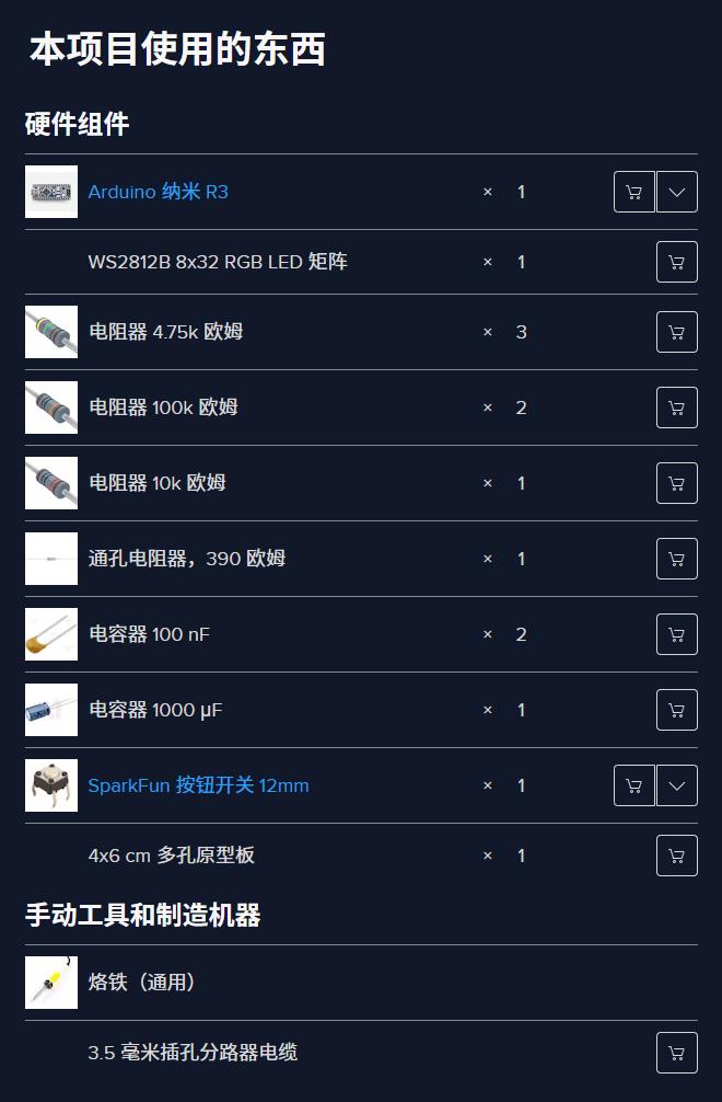
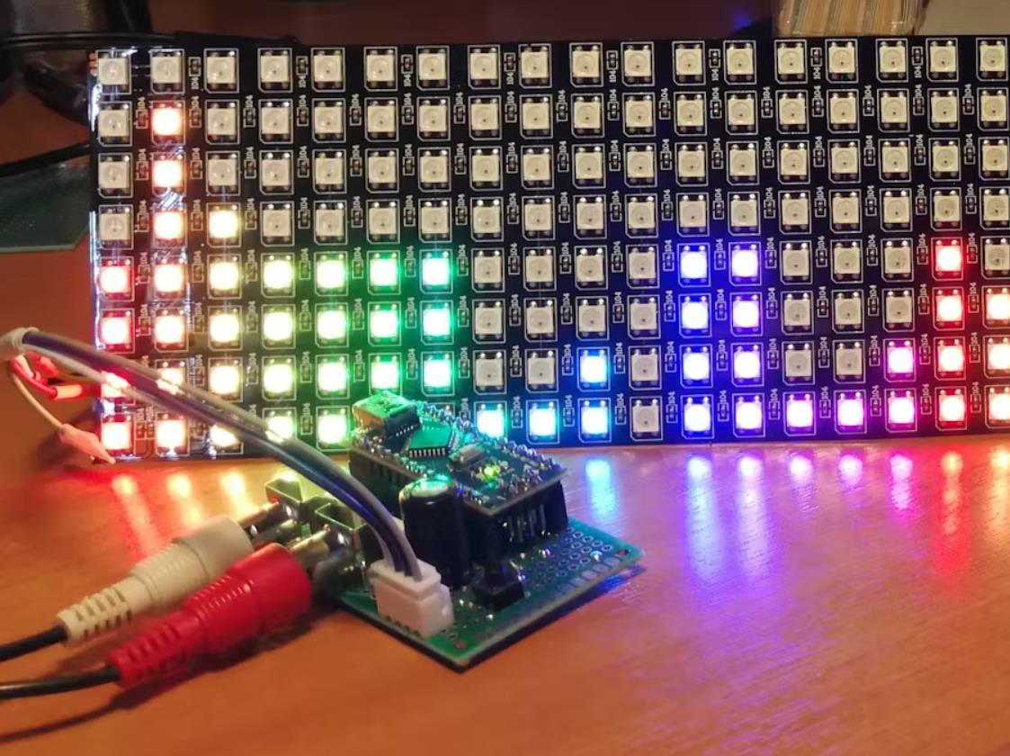
该项目用于使用 Arduino Nano 和 8x32 WS2812B RGB Led 矩阵制作 RGB 32 频段音频(音乐)频谱可视化器。
激发此灵感的原始项目
非常感谢基于MAX72xx LED矩阵的原始项目的作者Shajeeb。我只是修改了 LED 矩阵的先导部分,使其适应 RGB WS2812B Led 矩阵。
原始项目链接:32 波段音频频谱可视化分析仪
WS2812B RGB LED 矩阵
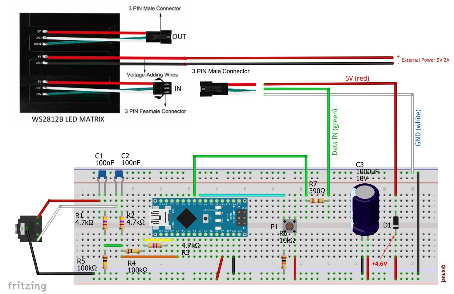
使用基于 5050 SMD 高亮度 LED 的 RGB LED 矩阵,有必要使用外部电源,因为 RGB 矩阵每个 LED 可以吸收超过 10mA 的电流,因此所有 LED 都以最大亮度点亮可以吸收超过 2.5 安培的电流。
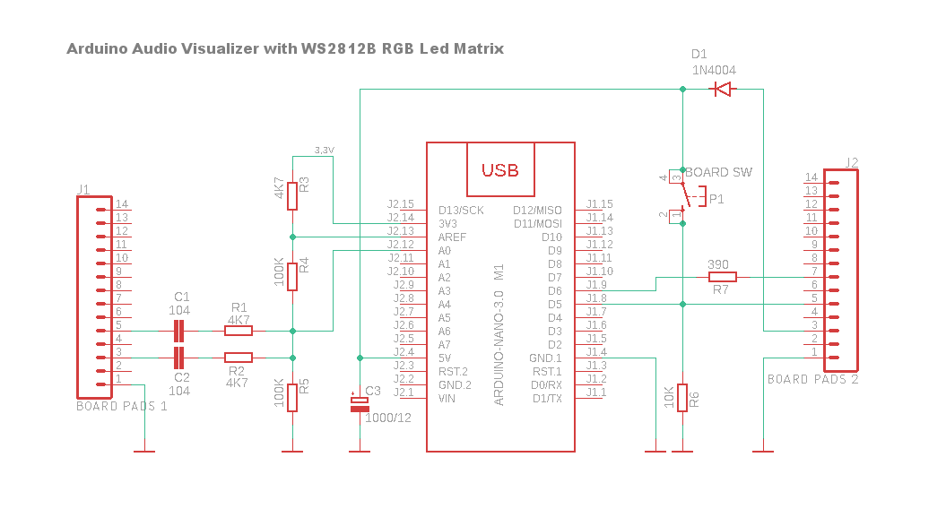
出于这个原因,我插入了一个 +5V 串联的二极管,以便在未连接 USB 电缆时能够在独立模式下为 Arduino 供电,并避免 Arduino 成为 RGB 矩阵的电源,从而避免电路板的内部电路过载它无法提供的电流。
在最初的项目中,除了输入二极管之外,为了保护 LED 矩阵输入免受可能的电压峰值的影响,我还在 Arduino 引脚 D6 和数据输入之间添加了一个串联的 390 欧姆电阻,以及一个 1000 μF 12V 电容器以提高 Arduino 电源电压稳定性。
硬件组装
如主照片所示,我使用两个 RCA 音频插座(直接焊接在板上)在 4x6 厘米多孔板上制作了第一个原型,也可以用 3.5 毫米母插孔插座代替。避免嗡嗡声的重要一点是使用屏蔽电缆在源和卡音频输入之间进行连接。另一个技巧是保持 Arduino 和 LED 矩阵之间的连接尽可能短。
代码
最后,所有软件都是基于采样程序的作者通过 FFT 库所做的出色工作和 Shajeeb 的最终实现。
我添加了两个功能:
第一个是 GetLedFromMatrix(...) 将矩阵映射到行和列中,并能够通过行和列坐标对 256 个 LED 中的每一个进行寻址。
第二个是那个 - 我任意地将其称为 SetColumn(... - 它根据音频数字化获得的峰值(值在 0 到 7 之间)和二维数组中的预设颜色打开每列的 LED。您可以根据自己的喜好更改值和颜色,从而获得乐趣。为了简化代码,我使用了一个名为 Wheel() 的 sobroutine(取自 Adafruit 的 Neopixel 库附加的演示),该例程从 0 到 255 之间的值开始返回一个无符号的 32 位长值,然后直接传递给 setPixelColor 函数。在这方面,您可以随意玩,同时牢记 Arduino 的内存限制,尽可能避免使用 32 位变量来存储 RGB 颜色值。
音频均衡
此外,由于我已经使用来自集成在 PC 主板中的声卡的音频运行了测试,为了改善频率响应,我添加了一个包含 32 个值的字节数组,这些值实际上构成了均衡曲线以衰减低音并增强高音。如果不需要,只需将EQ_ON变量设置为false或通过更改eq[32]数组的32个值来更改衰减级别 ,值100使幅度保持不变,小于100的衰减,大于100的值强调频段。
LED亮度
矩阵的亮度在代码中预设为 32(BRIGHTNESS 常量)。WS2812B矩阵的最大亮度值(在纸上)是 255,但值已经大于 100,不幸的是,LED 灯从白色变成淡黄色,可能需要通过两根中央的红色和黑色电线而不是在右侧连接器上为矩阵供电。
我还在努力......
最后,如果使用最大亮度64,1A电源可能就足够了,否则2A是必不可少的。
未来表达
我正在开发一个使用 OpenMusicLabs FHT 库的新版本,结果证明它比 Arduino FFT 快很多倍。
敬请期待。:)
请原谅我的英语不好,我用了谷歌翻译器。
项目代码
/*
  Copyright (c) 2019 Shajeeb TM

  Permission is hereby granted, free of charge, to any person obtaining a copy
  of this software and associated documentation files (the "Software"), to deal
  in the Software without restriction, including without limitation the rights
  to use, copy, modify, merge, publish, distribute, sublicense, and/or sell
  copies of the Software, and to permit persons to whom the Software is
  furnished to do so, subject to the following conditions:
  The above copyright notice and this permission notice shall be included in all
  copies or substantial portions of the Software.
  THE SOFTWARE IS PROVIDED "AS IS", WITHOUT WARRANTY OF ANY KIND, EXPRESS OR
  IMPLIED, INCLUDING BUT NOT LIMITED TO THE WARRANTIES OF MERCHANTABILITY,
  FITNESS FOR A PARTICULAR PURPOSE AND NONINFRINGEMENT. IN NO EVENT SHALL THE
  AUTHORS OR COPYRIGHT HOLDERS BE LIABLE FOR ANY CLAIM, DAMAGES OR OTHER
  LIABILITY, WHETHER IN AN ACTION OF CONTRACT, TORT OR OTHERWISE, ARISING FROM,
  OUT OF OR IN CONNECTION WITH THE SOFTWARE OR THE USE OR OTHER DEALINGS IN THE
  SOFTWARE.

  WS2812B Led Matrix vesion by Janux
*/

#include <arduinoFFT.h>
#include <SPI.h>
#include <Adafruit_NeoPixel.h>

#define SAMPLES 64        //Must be a power of 2
#define  xres 32          // Total number of  columns in the display, must be <= SAMPLES/2
#define  yres 8           // Total number of  rows in the display
#define ledPIN 6          // pint to control Led Matrix
#define NUM_LEDS (xres * yres)
#define BRIGHTNESS 32
#define buttonPin 5       // the number of the pushbutton pin to change displaycolor

byte yvalue;
byte displaycolumn, displayvalue;
int peaks[xres];
byte state = HIGH;           // the current reading from the input pin
byte previousState = LOW;    // the previous reading from the input pin
byte displaycolor = 0;

//Arrays for samplig
double vReal[SAMPLES];
double vImag[SAMPLES];
byte data_avgs[xres];
arduinoFFT FFT = arduinoFFT(); // FFT object

unsigned long lastDebounceTime = 0;   // the last time the output pin was toggled
unsigned long debounceDelay = 100;    // the debounce time; increase if the output flickers

// Parameter 1 = number of leds in matrix
// Parameter 2 = pin number (most are valid)
// Parameter 3 = pixel type flags, add together as needed:
//   NEO_KHZ800  800 KHz bitstream (most NeoPixel products w/WS2812 LEDs)
//   NEO_KHZ400  400 KHz (classic 'v1' (not v2) FLORA pixels, WS2811 drivers)
//   NEO_GRB     Pixels are wired for GRB bitstream (most NeoPixel products)
//   NEO_RGB     Pixels are wired for RGB bitstream (v1 FLORA pixels, not v2)
Adafruit_NeoPixel pixel = Adafruit_NeoPixel(NUM_LEDS, ledPIN, NEO_GRB + NEO_KHZ800);

// EQ filter to attenuates bass and improves treble
// Useful on PC sound card which usually has many bass and poor high frequency
bool EQ_ON = true; // set to false to disable eq
byte eq[32] = {50, 55, 60, 70, 75, 80, 85, 95,
               100, 100, 100, 100, 100, 100, 100, 100,
               100, 100, 100, 100, 100, 100, 100, 100,
               115, 125, 140, 160, 185, 200, 225, 255
              };

//Define color for single led, used in setColumn function, 0 for custom color
//Color are calculated by Wheel function, see below
byte colors[][8] = {
  {170, 160, 150, 140, 130, 120, 1, 1},
  {1, 5, 10, 15, 20, 25, 90, 90},
  {90, 85, 80, 75, 70, 65, 1, 1},
  {90, 90, 90, 30, 30, 30, 1, 1},
  {170, 160, 150, 140, 130, 120, 0, 0},
  {170, 160, 150, 140, 130, 120, 1, 1},
  {170, 160, 150, 140, 130, 120, 1, 1}
};

void setup() {

  pixel.begin();
  pixel.setBrightness(BRIGHTNESS);

  // Begin FFT operations
  ADCSRA = 0b11100101;      // set ADC to free running mode and set pre-scalar to 32 (0xe5)
  ADMUX = 0b00000000;       // use pin A0 and external voltage reference
}

void loop() {

  // ++ Sampling
  for (int i = 0; i < SAMPLES; i++) {
    while (!(ADCSRA & 0x10));       // wait for ADC to complete current conversion ie ADIF bit set
    ADCSRA = 0b11110101 ;           // clear ADIF bit so that ADC can do next operation (0xf5)
    int value = ADC - 512 ;         // Read from ADC and subtract DC offset caused value
    vReal[i] = value / 8;           // Copy to bins after compressing
    vImag[i] = 0;
  }

  FFT.Windowing(vReal, SAMPLES, FFT_WIN_TYP_HAMMING, FFT_FORWARD);
  FFT.Compute(vReal, vImag, SAMPLES, FFT_FORWARD);
  FFT.ComplexToMagnitude(vReal, vImag, SAMPLES);

  // -- FFT
  // ++ re-arrange FFT result to match with no. of columns on display (xres)
  int step = (SAMPLES / 2) / xres;
  int c = 0;
  for (int i = 0; i < (SAMPLES / 2); i += step) {
    data_avgs[c] = 0;
    for (int k = 0 ; k < step ; k++) {
      data_avgs[c] = data_avgs[c] + vReal[i + k];
    }
    data_avgs[c] = data_avgs[c] / step;
    c++;
  }

  // ++ send to display according measured value
  for (int i = 0; i <xres; i++) {
    if (EQ_ON)
      data_avgs[i] = data_avgs[i] * (float)(eq[i]) / 100; //apply eq filter
    data_avgs[i] = constrain(data_avgs[i], 0, 80);        // set max & min values for buckets to 0-80
    data_avgs[i] = map(data_avgs[i], 0, 80, 0, yres);     // remap averaged values to yres 0-8
    yvalue = data_avgs[i];
    peaks[i] = peaks[i] - 1;                              // decay by one light
    if (yvalue > peaks[i]) peaks[i] = yvalue;             //save peak if > previuos peak
    yvalue = peaks[i];
    displaycolumn = i;
    displayvalue = yvalue;
    setColumn(displaycolumn, displayvalue);               // draw buckets
  }
  pixel.show();                                           // show buckets
  displaycolorChange();                                   // check if button pressed to change color mode
}

//-----------------------------------------------------------------
// Light leds of x column according to y value
void setColumn(byte x, byte y) {
  byte led, i;

  for (i = 0; i < yres; i++) {
    led = GetLedFromMatrix(x, i); //retrieve current led by x,y coordinates
    if (peaks[x] > i) {
      switch (displaycolor) {
        case 4:
          //put zero 0 on array value to customize peaks color
          if (colors[displaycolor][i] > 0) {
            //normal color defined on color array
            pixel.setPixelColor(led, Wheel(colors[displaycolor][i]));
          }
          else {
            //custom color for peaks only with 0 on array value
            pixel.setPixelColor(led, 255, 255, 255); //Led number, R, G, B values
          }
          break;

        case 5:
          //change color by column
          pixel.setPixelColor(led, Wheel(x * 16));
          break;

        case 6:
          //change color by row
          pixel.setPixelColor(led, Wheel(i * 36));
          break;

        default:
          //display color set -> displaycolor from 0 to 3
          //color are defined on color array
          pixel.setPixelColor(led, Wheel(colors[displaycolor][i]));
      }//END SWITCH
    }
    else {
      pixel.setPixelColor(led, 0);
    }
  }
}

//======================================================================
// Calculate a led number by x,y coordinates
// valid for WS2812B with serpentine layout placed in horizzontal
// and zero led at bottom right (input connector on the right side)
// input value: x=0-31, y=0-7, return a led number from 0 to 255
//========================================================================
byte GetLedFromMatrix(byte x, byte y) {
  x = xres - x - 1;
  if (x & 0x01) {
    //Odd columns increase backwards
    return ((x + 1) * yres - y - 1);
  }
  else {
    //Even columns increase normally
    return ((x + 1) * yres - yres + y);
  }
}
//========================================================================

void displaycolorChange() {
  int reading = digitalRead(buttonPin);
  if (reading == HIGH && previousState == LOW && millis() - lastDebounceTime > debounceDelay) // works only when pressed
  {
    displaycolor++;
    if (displaycolor > 6) displaycolor = 0;
    lastDebounceTime = millis();
  }
  previousState = reading;
}

/* Utility from Adafruit Neopixel demo sketch
   Input a value 0 to 255 to get a color value.
   The colours are a transition R - G - B - back to R.*/
unsigned long Wheel(byte WheelPos) {
  WheelPos = 255 - WheelPos;
  if (WheelPos < 85) {
    return pixel.Color(255 - WheelPos * 3, 0, WheelPos * 3);
  }
  if (WheelPos < 170) {
    WheelPos -= 85;
    return pixel.Color(0, WheelPos * 3, 255 - WheelPos * 3);
  }
  WheelPos -= 170;
  return pixel.Color(WheelPos * 3, 255 - WheelPos * 3, 0);
}
【Arduino 动手做】RGB 32 频段音频频谱可视化器
项目链接:https://www.hackster.io/janux/rgb-32-band-audio-spectrum-visualizer-0f26e0
项目作者:贾努克斯
项目代码:https://www.hackster.io/code_files/451978/download
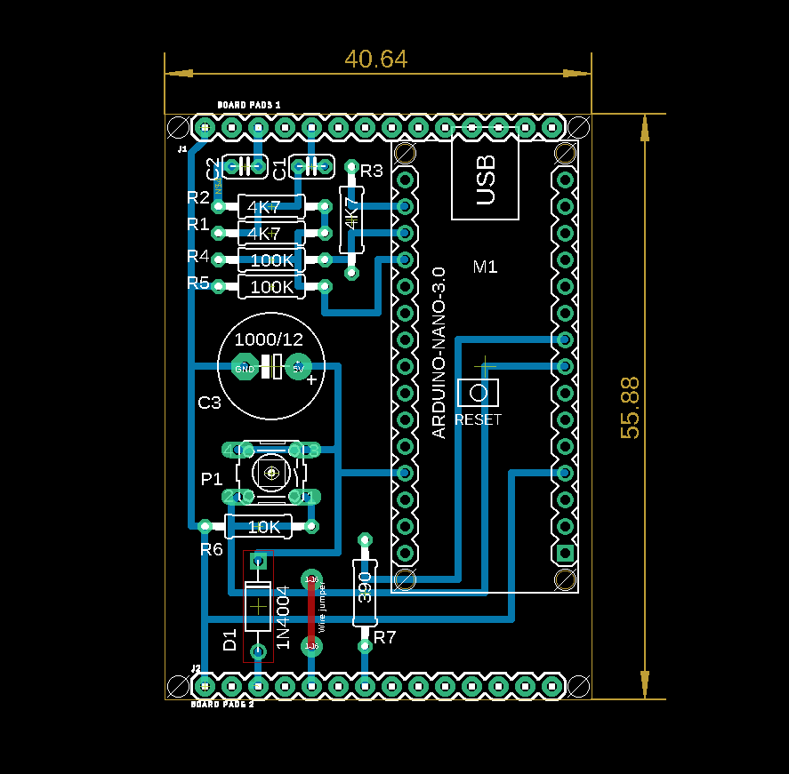
PCB 文件:https://hacksterio.s3.amazonaws.com/uploads/attachments/1132831/arduino_rgb_audio_analyzer_lX4Dv4Pta2.zip


 他的勋章
他的勋章
评论