 返回首页
返回首页
 回到顶部
回到顶部
BaseCam 无刷云台控制器 (BGC) 系列产品广泛用于电影摄影行业的相机云台控制和稳定系统,此处提供了 YouTube 介绍性视频:
• BaseCam Electronics 简介
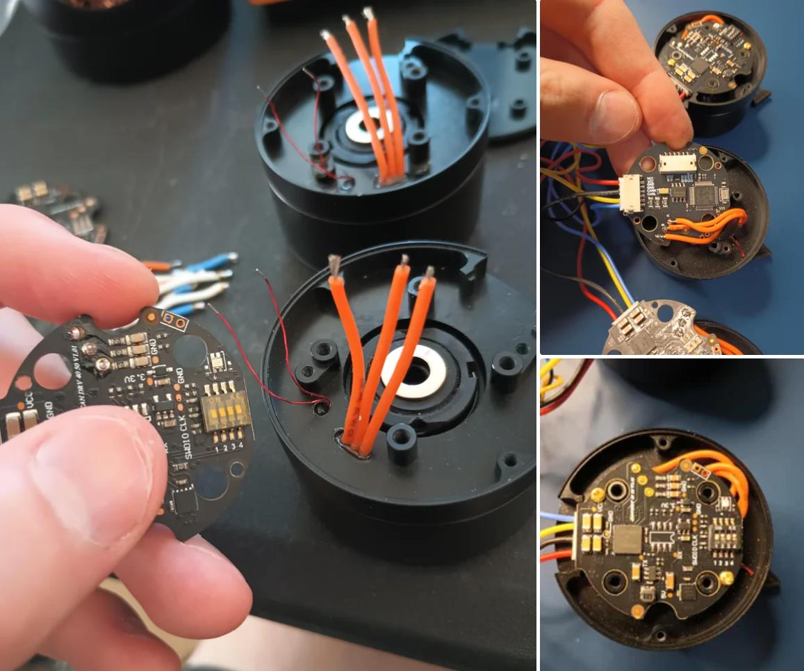
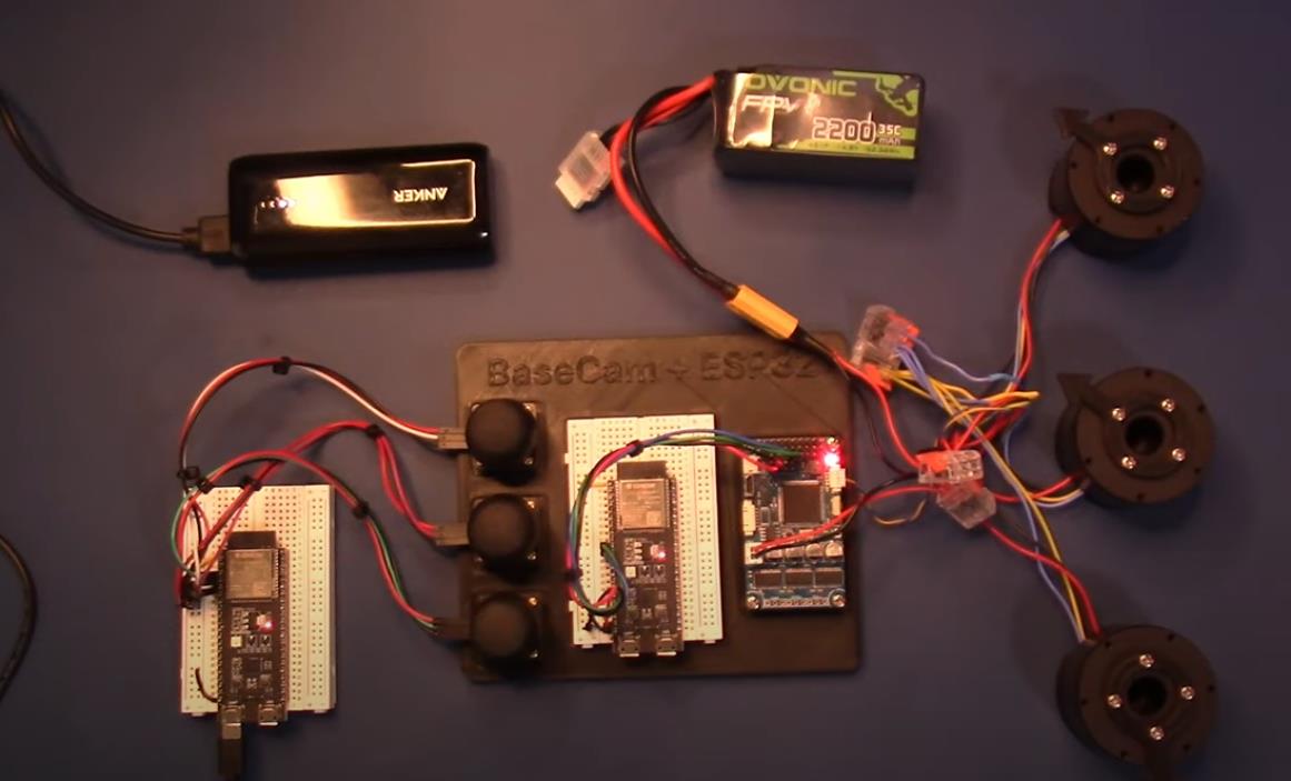
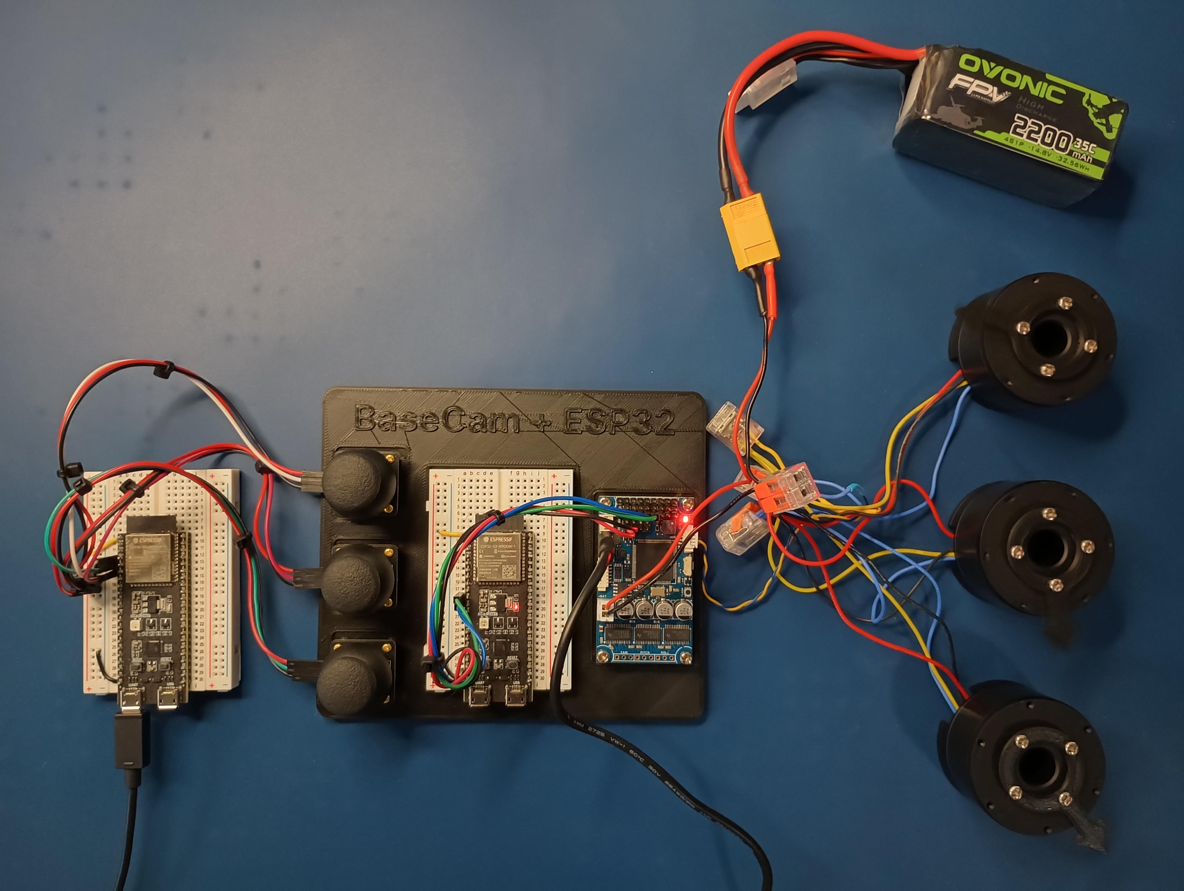
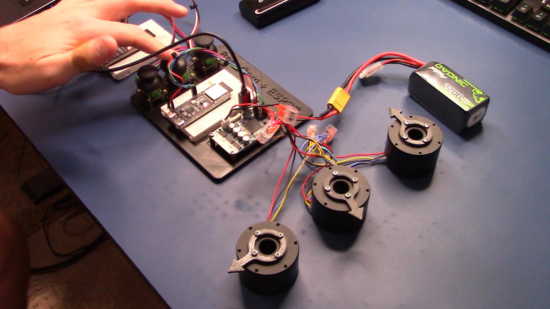
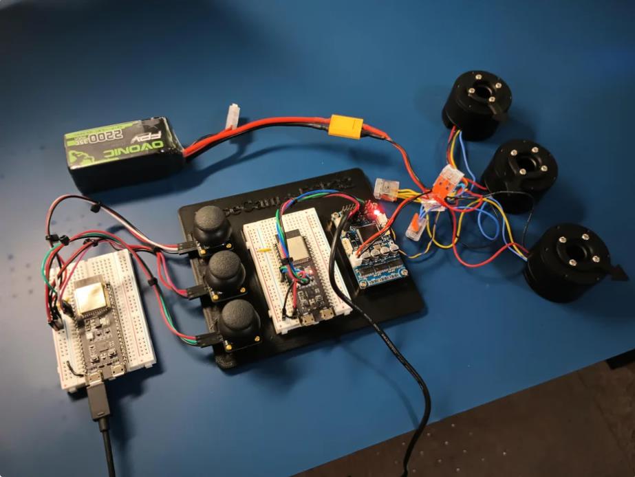
除了让 3 个 DM5005 万向节电机对 BaseCam Extended Long 控制器板上的板载 IMU 做出反应外,我还希望能够读取和处理来自 3 个独立单轴纵杆的信号,以通过 BaseCam 控制器板控制这些相同万向节电机的滚动、俯仰和偏航。为此,我使用 ESP32 微控制器从纵杆读取输入,并将这些值中继到 BaseCam 控制器,一种情况下是直接有线,另一种情况下是通过 2 个 ESP32 板使用低功耗蓝牙 (BLE) 无线传输。
BaseCam 系列万向节控制器具有接收不同信号类型的功能,包括 PWM 和模数 (ADC) 读数。但是,我希望通过 ESP32-S3 开发板来控制信号在 BaseCam 控制器读入之前的处理方式。该项目的布线和设置允许进行这种类型的控制,无论是直接有线还是使用 BLE 无线。我希望它对您的下一个 BaseCam 项目有用!
用品
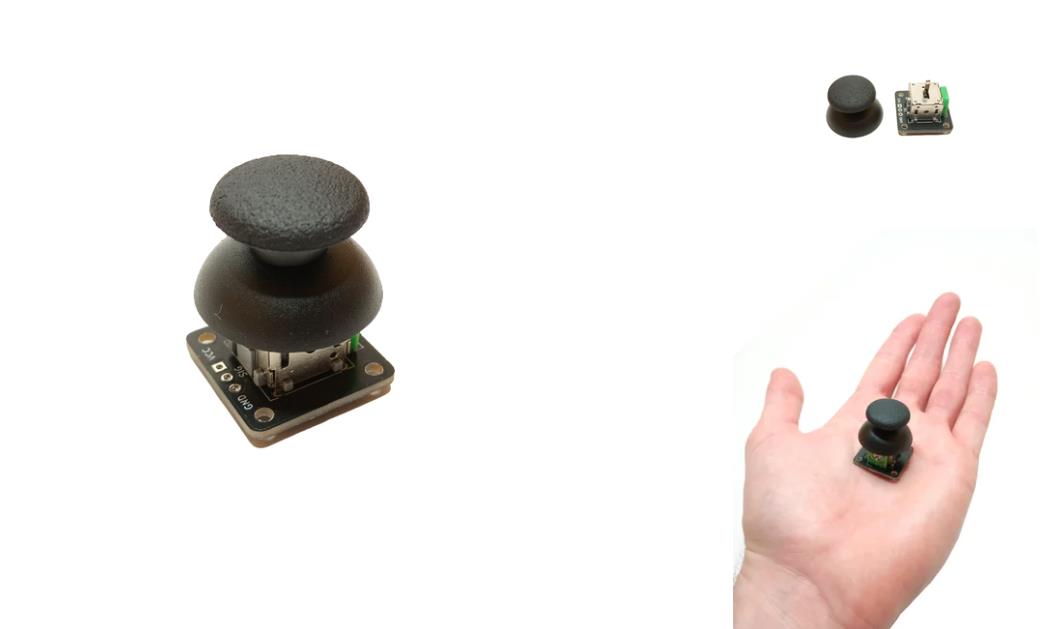
1.3 x 单轴纵杆模块
2.2 x ESP32-S3 DevKitC 开发板
3.1 x Basecam BGC Extended Long 控制器
4.1 x 面包板
5.1 x 22AWG 实心线
6.1 x 各种多色热缩管
7.1 x 各种跳线
8.2 x Micro-USB 转 USB-A 电缆
9.1 x 1.25mm 预压接连接器套件(用于 BaseCam Extended Long 板的 CANbus 连接器)
10.1 x 烙铁
11.1 x 焊料卷
12.1 x 电池组
13.1 x 各种预压接 ZH 1.5mm 连接器(用于 CAN 驱动板)
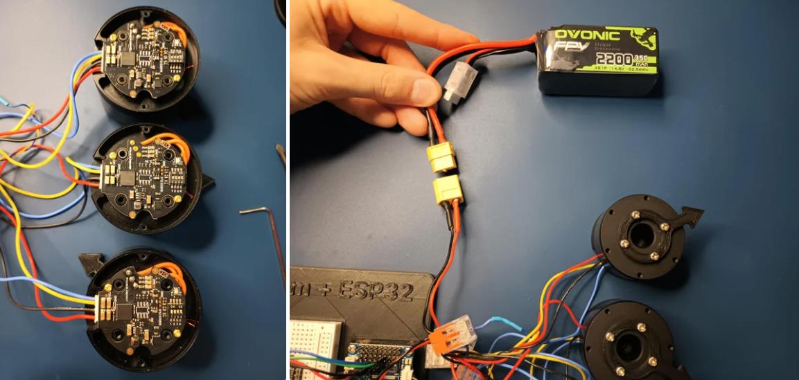
14.1 x 4S 锂聚合物 (LiPo) 电池
15.1 x XT-60 电池连接器
16.1 个 2 针 JST-XH 连接器,用于将 LiPo 电池连接到 BaseCam 电池针脚
17.1 x 各种 M2 黄铜支座和螺钉套装(用于演示组装)
18.1 台 FDM 3D 打印机
19.1 x 1 千克卷轴 1.75 毫米厚的黑色 PLA+ 线材
20.1 x 各种夹式线连接器(可选,可用于原型设计)
21.1 x 扎带套装(可选,用于电线管理)
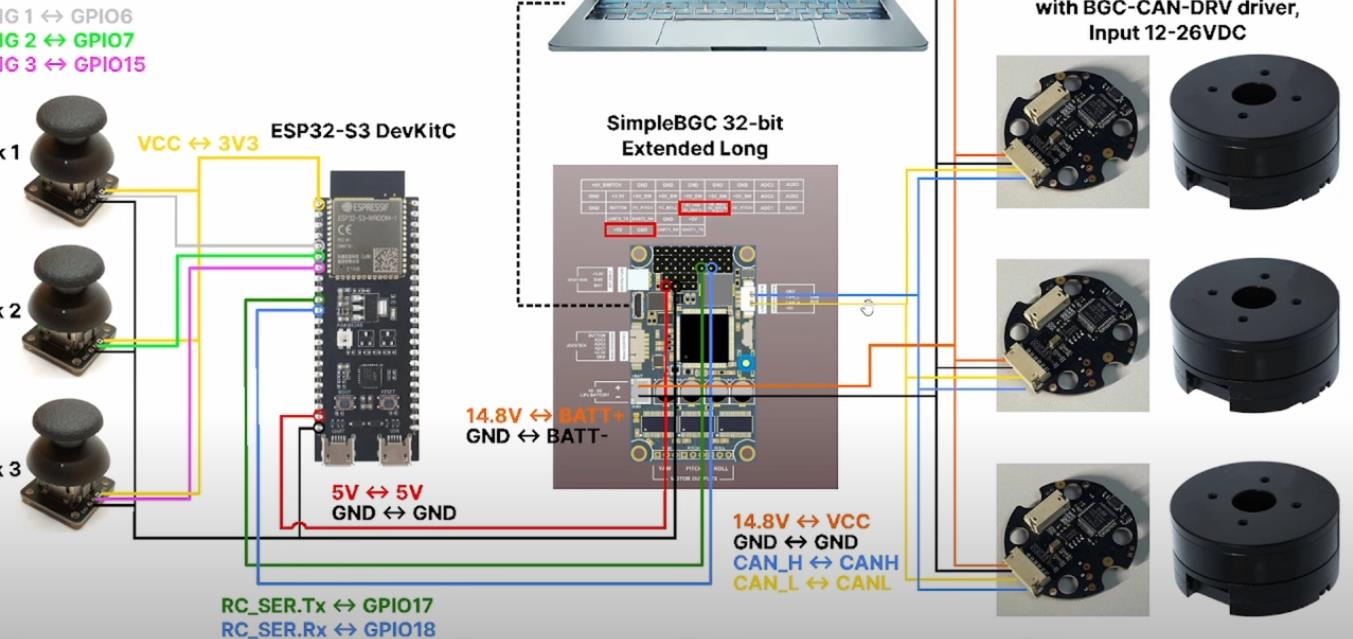
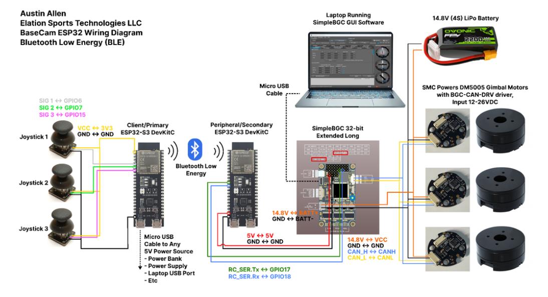
对于仅使用 1 个 ESP32-S3 开发板读取数据的情况,3 个单轴摇杆将 3 个摇杆中的每一个的 VCC 和 GND 分别连接到 ESP32 板上的 3V3 和 GND。摇杆模块充当弹簧加载的电位器,因此我们将使用具有模数转换 (ADC) 功能的 ESP32 引脚(GPIO4、GPIO5、GPIO6)。我们将使用 ESP32 上的硬件 Serial1 引脚(GPIO17、GPIO18)连接到 BaseCam 控制器板上的 UART1_RX、UART1_TX 引脚。请注意,ESP32 上的 RX 引脚连接到 BaseCam 板上的 TX 引脚,反之亦然。如果您想从 BaseCam 板为 ESP32 供电,请将两块板上的 5V 引脚连接在一起,然后将两块板上的 GND 引脚连接在一起。将 BaseCam 板连接到您的计算机以提供 5V 电源,并在 BaseCam Simple GUI 软件和控制器板之间进行通信。
引脚连接摘要:
ESP32 GPIO6 - 摇杆 #1 SIG 引脚(白色)
ESP32 GPIO7 - 摇杆 #2 SIG 引脚(绿色)
ESP32 GPIO15 - 摇杆 #3 SIG 引脚(紫色)
ESP32 RX (GPIO18) - BaseCam UART1_TX 引脚(蓝色)
ESP32 TX (GPIO17) - BaseCam UART1_RX 引脚(绿色)
ESP32 5V 引脚 - BaseCam 5V 引脚(红色)
ESP32 3V3 引脚 - 连接到所有 3 个摇杆 VCC 引脚(黄色)
ESP32 GND 引脚 - 连接到所有 3 个纵杆 GND 引脚,以及 BaseCam GND 引脚(黑色)
电池正极(红色)端子 - 并联连接到所有 3 个万向节电机驱动器的 VCC 引脚,以及 BaseCam 板上的 +BAT 引脚。
电池负极(黑色)端子 - 并联连接到所有 3 个万向节电机驱动器的 GND 引脚,以及 BaseCam 板上的电池 GND 引脚(正极 BAT+ 引脚下方)。
BaseCam CAN_H 针 - 与 CANH 针并联,全部在所有 3 个云台电机驱动器上(黄线)
BaseCam CAN_L 针 - 与 CANL 针并联,全部在所有 3 个云台电机驱动器上(蓝线)
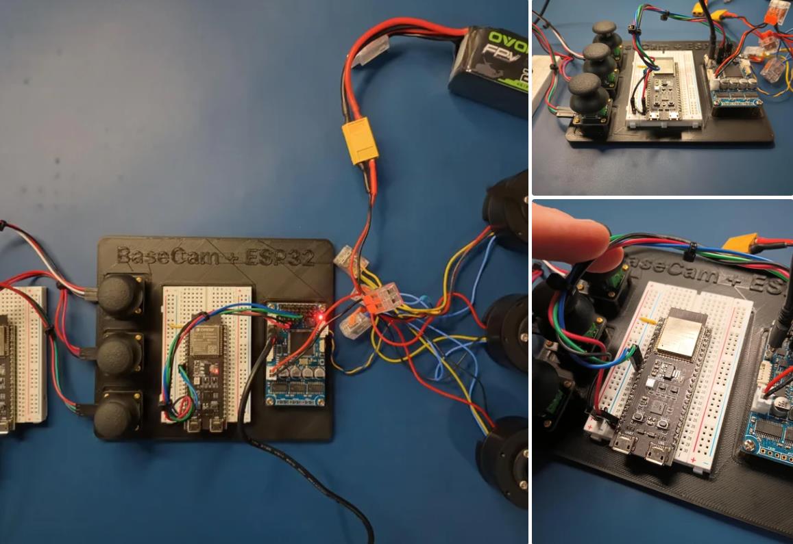
对于使用 2 个 ESP32 将摇杆信息中继到 BaseCam 控制器的情况下,第一个客户端/主 ESP32 读取 3 个摇杆,并将这些读数持续发送到第二个外设/从属 ESP32,后者又使用 BaseCam API 将它们中继到 BaseCam 控制器。在布线方面,这只是意味着从外设 ESP32 上移除 3 个摇杆连接,而是将它们连接到客户端 ESP32。所有其他接线与 Direct Wiring 情况相同。此外,主客户端 ESP32-S3 开发板可以由任何 5V 电源供电,例如电池组、笔记本电脑 USB 端口或通过 micro-USB 转 USB-A 电缆的壁挂式 5VDC 电源。
该项目成功演示了如何将命令从 ESP32-S3 开发板发送到 BaseCam 云台控制器板,以便通过 CANbus 连接控制云台电机。您也可以通过低功耗蓝牙将信号从一个 ESP32 发送到另一个 ESP32,为您的 BaseCam 控制器添加无线功能!
以下是进一步推进此项目的一些想法:
构建具有三个或更多轴的自定义完整万向节组件,并将此处提到的电子设备合并到该组件中。这可用于远程控制的摄像机监控、电影摄影、机器人遥测等。
添加基于 ESP32 的电容式触摸屏模块,带有屏幕按钮和文本字段,用于创建、更改、保存和修改发送到 BaseCam 控制板的设置和命令。
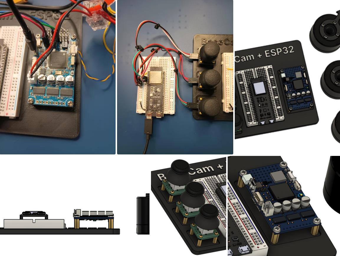
设计并 3D 打印一个外壳,以容纳客户端 ESP32 模块和用户界面设备(纵杆等),以创建便携式电池供电的万向节控制器。
使用 KiCAD 设计和使用基于 ESP32 的定制 PCB。
试验各种输入设备,如电位计旋钮、触觉开关和其他输入传感器和开关,以扩展用户与 BaseCam 板的交互方式。
使用一对带有 EMT 导管的耦合器创建一个可伸缩的 EMT 导管监控杆,并在杆顶部附近安装一个摄像头万向节,并沿杆安装控制电子设备。
项目代码
/*
Elation Sports Technologies LLC
Austin Allen
24 Jun 2024

BaseCam ESP32-S3 BLE Client/Master Code

The Client/Master ESP32 constantly reads joystick values values and
sends them out over BLE. The Slave ESP32 receives those 3 x integers
and sends corresponding serial commands to the SimpleBCG using the
BaseCam Serial API.

The Peripheral/slave ESP32 is running a PlatformIO project code
in order to utilize the most up-to-date Basecam Serial API.
That code is modified from the MimicControl Arduiuno example on
the BaseCam Github:
https://github.com/basecamelectronics/sbgc32-serial-api/tree/master/examples/Arduino/MimicControl

*/

#include <BLEDevice.h>

bool serial_debug_output_bool = true;

static String targetDeviceName = "ESP32_S3_BLE"; //Set this string to the name you assigned to the slave ESP32 in its code.
static BLERemoteCharacteristic* pTxCharacteristic;

// Master ESP32 UUIDs (update to match the slave ESP32)
static BLEUUID serviceUUID("4fafc201-1fb5-459e-8fcc-c5c9c331914b");
static BLEUUID charUUID("beb5483e-36e1-4688-b7f5-ea07361b26a8");

// Callback function to handle BLE notifications, i.e. the stuff coming back from the Peripheral/Slave ESP32.
// For this project, there isn't anything coming back from the Peripheral/Slave ESP32.
class MyCallbacks : public BLECharacteristicCallbacks {
    //Just print out any feedback that gets sent back from the slave ESP32.
    void onRead(BLECharacteristic* pCharacteristic) {
      0;
      //Serial.print("Received data: ");
      //Serial.println(pCharacteristic->getValue().c_str());
    }
};

//Joystick-related variables
//Pin definitions
const int pin_joy_x = 4;
const int pin_joy_y = 5;
const int pin_joy_z = 6;
int joystick_initial_x = 0; //Initial readings
int joystick_initial_y = 0;
int joystick_initial_z = 0;
int joystick_value_x = 0;
int joystick_value_y = 0;
int joystick_value_z = 0;
int joystick_deadzone_x = 30;
int joystick_deadzone_y = 30;
int joystick_deadzone_z = 30;

String BLE_data_to_send = "0,0,0";
bool device_found_bool = false;

String output_text = "";

void grab_initial_readings(){
  joystick_initial_x = analogRead(pin_joy_x);
  joystick_initial_y = analogRead(pin_joy_y);
  joystick_initial_z = analogRead(pin_joy_z);
}

void read_joysticks(){
  joystick_value_x = analogRead(pin_joy_x) - joystick_initial_x;
  joystick_value_y = analogRead(pin_joy_y) - joystick_initial_y;
  joystick_value_z = analogRead(pin_joy_z) - joystick_initial_z;
  if (abs(joystick_value_x) < joystick_deadzone_x){
    joystick_value_x = 0;
  }
  if (abs(joystick_value_y) < joystick_deadzone_y){
    joystick_value_y = 0;
  }
  if (abs(joystick_value_z) < joystick_deadzone_z){
    joystick_value_z = 0;
  }

  ////Serial.println(String(joystick_value_x) + "," + String(joystick_value_y) + "," + String(pin_joy_z));
}

void setup() {

  if (serial_debug_output_bool){
    Serial.begin(115200);
    while(!Serial){
      0;
    }
    Serial.println("Serial debug communication established.");
  }

  //Joystick pins
  pinMode(pin_joy_x,INPUT);
  pinMode(pin_joy_y,INPUT);
  pinMode(pin_joy_z,INPUT);

  grab_initial_readings();

  //Look for the slave ESP32 over BLE.
  output_text = "Searching: " + String(targetDeviceName);
  if (serial_debug_output_bool) Serial.println("Searching for ESP32 with device name: " + String(targetDeviceName) + " for a few seconds...");

  // Initialize the BLE device
  BLEDevice::init("");

  // Start scanning for BLE devices
  BLEScan* pBLEScan = BLEDevice::getScan();
  pBLEScan->setActiveScan(true);
  BLEScanResults foundDevices = pBLEScan->start(3); // Scan for 3 seconds

  //Serial.print("Devices found: ");
  //Serial.println(foundDevices.getCount());
  //Serial.println("----------------------------");

  bool deviceConnected = false;

  for (int i = 0; i < foundDevices.getCount(); i++) {
    BLEAdvertisedDevice device = foundDevices.getDevice(i);
    if (device.haveName() && device.getName().compare(targetDeviceName.c_str()) == 0) {
      if (serial_debug_output_bool) Serial.println("Found the Peripheral/Slave ESP32!");

      BLEClient* pClient = BLEDevice::createClient();
      if (pClient->connect(&device)) {
        if (serial_debug_output_bool) Serial.println("Connected to the Peripheral/Slave ESP32");

        BLERemoteService* pRemoteService = pClient->getService(serviceUUID);
        if (pRemoteService != nullptr) {
          pTxCharacteristic = pRemoteService->getCharacteristic(charUUID);

          if (pTxCharacteristic != nullptr && pTxCharacteristic->canWrite()) {
            deviceConnected = true;
            //Serial.println("Successfully connected to the service and characteristic on the slave ESP32");
            break; // Exit the loop as the device is connected
          } else {
            //Serial.println("Characteristic not found or not writable");
          }
        } else {
          //Serial.println("Service not found");
        }
      } else {
        0;
        //if (serial_debug_output_bool) Serial.println("Failed to connect");
      }
    }
  }

  if (!deviceConnected) {
    if (serial_debug_output_bool) Serial.println("Failed to connect to the Peripheral/Slave ESP32. Please restart to try again.");
    if (serial_debug_output_bool) Serial.println("Also, check that the peripheral ESP32's code - its BLE_Mode_boolean variable must be set to true to enable BLE connection.");
    //output_text = "BLE connect failed, restart the Client/Master ESP32 to try connecting again...";
    while (true) {
      delay(1000); // Keep the program in an infinite loop if not connected
    }
  }

  output_text = "BLE connect success!";
  if (serial_debug_output_bool) Serial.println(output_text);
  output_text = "Connected to " + String(targetDeviceName);
  if (serial_debug_output_bool) Serial.println(output_text);
  delay(500);

  if (serial_debug_output_bool) Serial.println("Initialization complete.");
  delay(500);

}

void loop() {
  //Read the 3 x joysticks, and send out the readings as one comma-delimited string over BLE
  //to the Peripheral/Slave ESP32.
  read_joysticks();
  BLE_data_to_send = String(joystick_value_x) + "," + String(joystick_value_y) + "," + String(joystick_value_z);
  if (pTxCharacteristic != nullptr) {
    if (serial_debug_output_bool) Serial.println("Sending: " + BLE_data_to_send);
    pTxCharacteristic->writeValue(BLE_data_to_send.c_str(), BLE_data_to_send.length());
  }
}
【Arduino 动手做】ESP32 + BaseCam 蓝牙云台控制
项目链接:https://www.instructables.com/ESP32-BaseCam-Bluetooth-Gimbal-Control/
项目作者:洛杉矶 Penguingineer
项目视频:https://www.youtube.com/watch?v=7FAC-9hZs3E
项目代码:https://github.com/TheESTest/BaseCam-ESP32-Controller
3D打印文件:
https://content.instructables.com/F5F/GMA9/LZCPTYUF/F5FGMA9LZCPTYUF.stl
https://content.instructables.com/FS9/VR2O/LZCPTYTN/FS9VR2OLZCPTYTN.stl
API 库:https://github.com/basecamelectronics/sbgc32-se-rial-ap
CAN 接线和通信协议文档:https://content.instructables.com/F9K/OFQO/LZCPTR48/F9KOFQOLZCPTR48.pdf


 他的勋章
他的勋章

评论