 返回首页
返回首页
 回到顶部
回到顶部
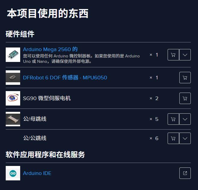
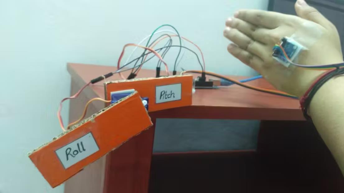
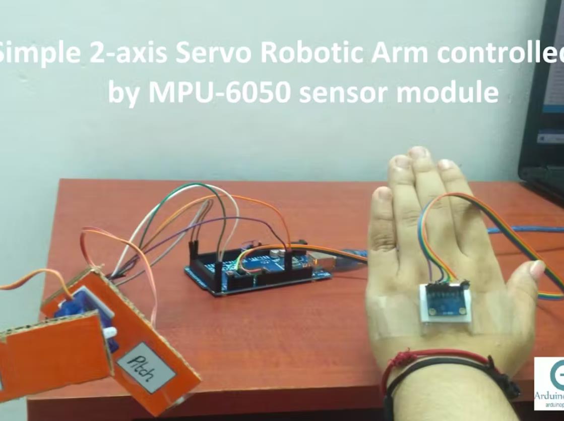
一个简单有趣的项目,您可以在其中使用 MPU6050(加速度计 + 陀螺仪)传感器模块来控制一个简单的 2 轴伺服机械臂。
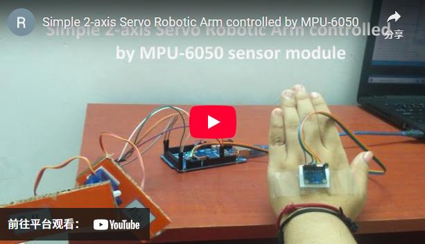
今天,我将向您解释 MPU-6050(加速度计+陀螺仪)传感器模块,以及如何通过它控制由微型伺服电机制成的 Simple 2 轴机械臂。
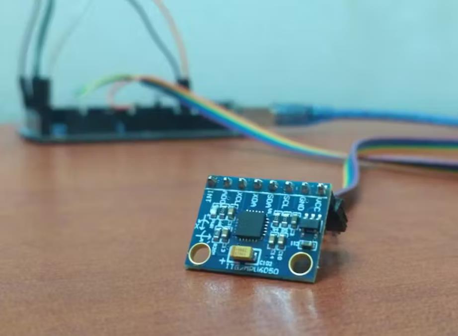
什么是 MPU-6050 传感器模块?
InvenSense MPU-6050 是一款低成本、高精度的惯性测量单元 (IMU),具有六个自由度 (DOF)。 IMU 可以测量加速度、惯性和许多其他参数,以便您确定它们的空间位置和速度。它在单个芯片中包含一个 MEMS 3 轴加速度计和一个 MEMS 3 轴陀螺仪。它还具有一个板载数字运动处理器 (DMP),可处理复杂的 6 轴 MotionFusion 算法。该传感器模块还能够通过辅助主 IIC 总线访问外部磁力计或其他传感器,以提供完整的 9 轴 MotionFusion 输出。MPU-6050 传感器模块也由一个温度传感器组成,但精度较低。
可以使用 MPU-6050 的示例
汽车行业 - 展开安全气囊、车辆侧倾处理
游戏控制器 - Wii 遥控器/ Wiimote
云台/相机稳定系统
硬盘
个人数字助理 - 智能手机、平板电脑
机器人
无人机 (UAV) - 无人机、直升机
车辆导航
加速度计
该设备用于测量加速度,即特定物体的速度变化率。以恒定速度运动的物体将具有零加速度。
MPU-6050 中的加速度计是三轴加速度计,这意味着它可以感应 X、Y 和 Z 轴上的加速度。
陀螺仪
这是 MPU-6050 中的另一个关键组件,可以测量角动量或围绕 X、Y 和 Z 轴的旋转。
MEMS 陀螺仪由三个传感器组成,每个轴一个,当它们旋转时会产生电压。该电压使用 16 位模数转换器进行内部采样。
引脚
VCC - 3.3V 直流电源
GND - 接地
SCL - 串行时钟
SDA - 串行数据
XDA - 辅助串行数据(当另一个传感器连接到此模块时使用)
XCL - 辅助串行时钟(当另一个传感器连接到此模块时使用)
AD0 - I2C 地址位。允许您更改 MPU-6050 模块的内部 I2C 地址。如果模块与另一个 I2C 设备冲突,或者您希望在同一 I2C 总线上使用两个 MPU-6050,则可以使用它。
INT - 中断输出
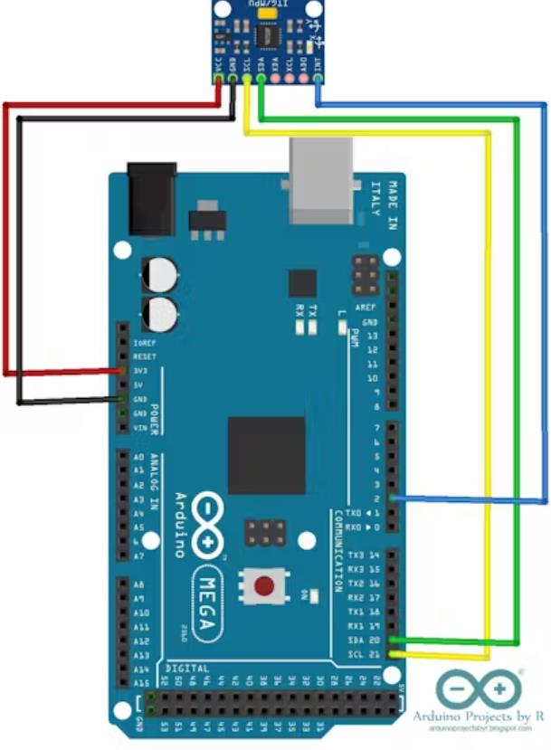
将 MPU-6050 传感器模块与 Arduino 连接
要将 MPU-6050 与 Arduino 连接,您将需要 Jeff Rowberg 的 I2C 开发库和 MPU-6050 库。 要了解有关这些库的更多信息,请访问 Jeff 的网站。
这些库将in.ZIP格式下载,您可以直接将这些文件夹添加到您的 Arduino IDE 中。
打开您的 Arduino IDE。
前往 素描 顶部菜单栏中的菜单。
选择 Include library (包括库)。
选择 Add.ZIP 库...选择。
导航到下载文件夹或保存the.ZIP库的任何其他文件夹并选择它。
您将在 Arduino IDE 底部看到一条消息,指出该库已添加到您的列表中。
重复这些步骤以添加第二个库。
现在您已经添加了两个基本库,请尝试打开一个示例 sketch 并将其上传到您的 Arduino 微控制器板。通过旋转 MPU-6050 传感器模块来试验它们,并观察串行监视器中显示的读数的变化。
设置
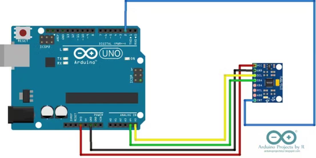
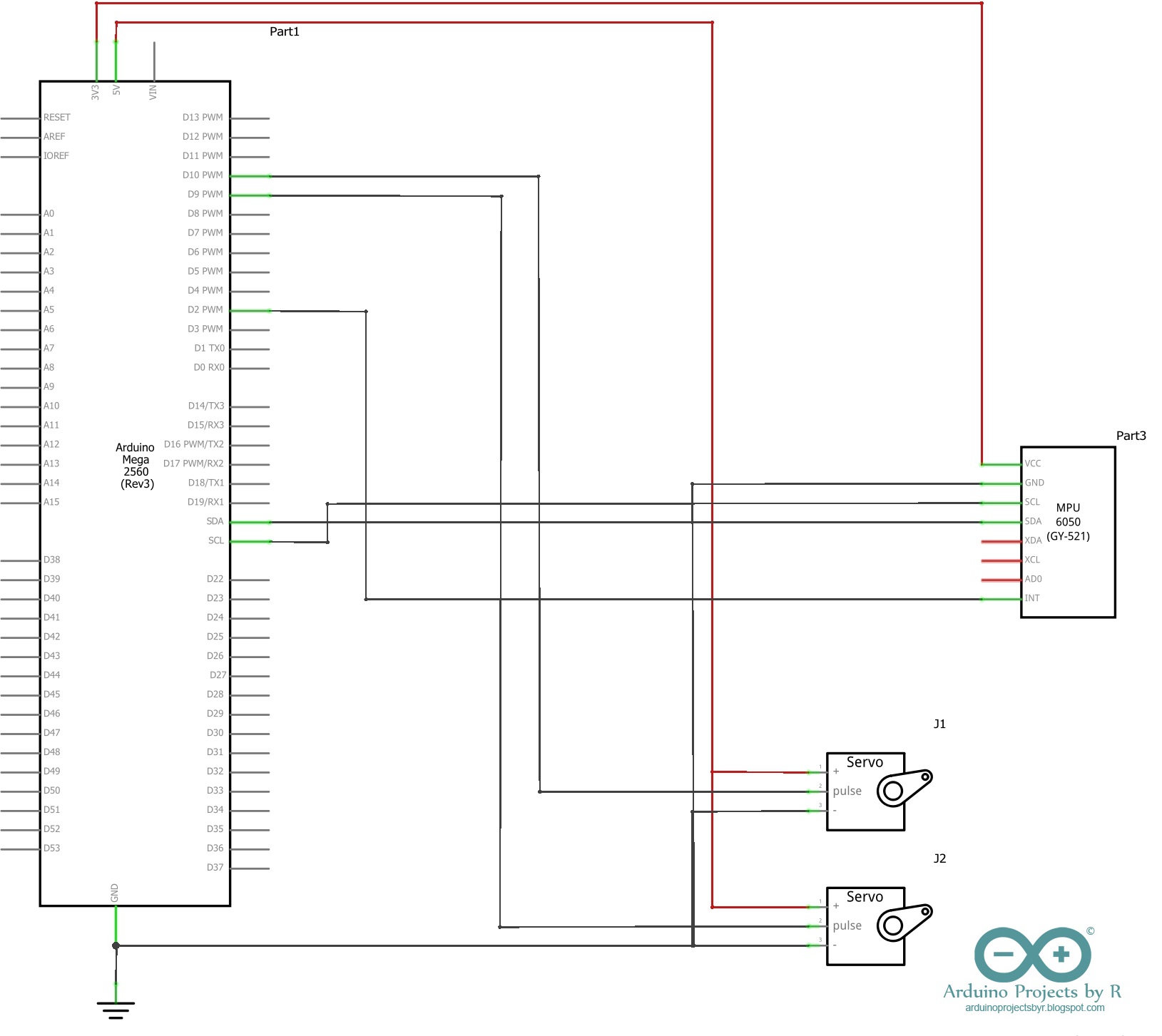
连接
*注意:原理图可以在 原理图 部分找到。
MPU-6050 传感器模块
VCC - 3.3V
GND - 接地
SDA - D20 (Arduino Mega 2560)、A4 (Arduino Uno 和 Nano)
标准及校正实验所 - D21 (Arduino Mega 2560)、A5 (Arduino Uno 和 Nano)
国际 - D2
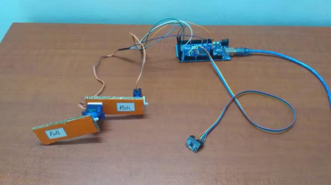
微型伺服电机(Roll)
S(黄色/橙色)- D9
+(红色)- 5V
- (黑色/棕色)- GND
微型伺服电机 (Pitch)
S(黄色/橙色)- D10
+(红色)- 5V
- (黑色/棕色)- GND
编码
正如我在上面已经提到的,您将需要 Jeff Rowberg 的 I2C 开发库和 MPU-6050 库来将您的 MPU-6050 传感器模块与 Arduino 微控制器板连接。要了解有关这些库的更多信息,请访问 Jeff 的网站。
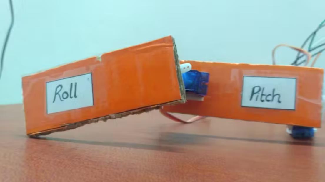
转到顶部菜单栏中的 File 菜单,然后从 MPU6050 库中选择 MPU6050_DMP6 样例 Sketch。将其上传到您的 Arduino 微控制器板,并观察传感器模块产生的读数。旋转传感器模块以注意变化并识别滚动、俯仰和偏航。Roll (纵轴)、pitch (横轴) 和 yaw (垂直轴) 是飞机主轴。
在这个项目中,我们将仅使用滚动和俯仰测量来控制简单的机械臂。机械臂由两个微型伺服电机制成,因此您需要微控制器的伺服库 来控制伺服电机的运动。
使用 attach( ) 函数声明伺服电机所连接的引脚,并在 void setup() 中将伺服电机的初始位置设置为零。如果您仔细阅读代码,您会注意到滚动测量值(以度为单位)表示为 ypr[2] * 180/M_PI。
旋转传感器模块并观察生成的测量值,以计算偏移量和范围。最后,您应该使用此范围将测量值映射到伺服电机的位置。
项目代码
// I2C device class (I2Cdev) demonstration Arduino sketch for MPU6050 class using DMP (MotionApps v2.0)
// 6/21/2012 by Jeff Rowberg <jeff@rowberg.net>
// Updates should (hopefully) always be available at https://github.com/jrowberg/i2cdevlib
//
// Changelog:
//      2013-05-08 - added seamless Fastwire support
//                 - added note about gyro calibration
//      2012-06-21 - added note about Arduino 1.0.1 + Leonardo compatibility error
//      2012-06-20 - improved FIFO overflow handling and simplified read process
//      2012-06-19 - completely rearranged DMP initialization code and simplification
//      2012-06-13 - pull gyro and accel data from FIFO packet instead of reading directly
//      2012-06-09 - fix broken FIFO read sequence and change interrupt detection to RISING
//      2012-06-05 - add gravity-compensated initial reference frame acceleration output
//                 - add 3D math helper file to DMP6 example sketch
//                 - add Euler output and Yaw/Pitch/Roll output formats
//      2012-06-04 - remove accel offset clearing for better results (thanks Sungon Lee)
//      2012-06-01 - fixed gyro sensitivity to be 2000 deg/sec instead of 250
//      2012-05-30 - basic DMP initialization working

/* ============================================
I2Cdev device library code is placed under the MIT license
Copyright (c) 2012 Jeff Rowberg

Permission is hereby granted, free of charge, to any person obtaining a copy
of this software and associated documentation files (the "Software"), to deal
in the Software without restriction, including without limitation the rights
to use, copy, modify, merge, publish, distribute, sublicense, and/or sell
copies of the Software, and to permit persons to whom the Software is
furnished to do so, subject to the following conditions:

The above copyright notice and this permission notice shall be included in
all copies or substantial portions of the Software.

THE SOFTWARE IS PROVIDED "AS IS", WITHOUT WARRANTY OF ANY KIND, EXPRESS OR
IMPLIED, INCLUDING BUT NOT LIMITED TO THE WARRANTIES OF MERCHANTABILITY,
FITNESS FOR A PARTICULAR PURPOSE AND NONINFRINGEMENT. IN NO EVENT SHALL THE
AUTHORS OR COPYRIGHT HOLDERS BE LIABLE FOR ANY CLAIM, DAMAGES OR OTHER
LIABILITY, WHETHER IN AN ACTION OF CONTRACT, TORT OR OTHERWISE, ARISING FROM,
OUT OF OR IN CONNECTION WITH THE SOFTWARE OR THE USE OR OTHER DEALINGS IN
THE SOFTWARE.
===============================================
*/

// I2Cdev and MPU6050 must be installed as libraries, or else the .cpp/.h files
// for both classes must be in the include path of your project
#include "I2Cdev.h"

#include "MPU6050_6Axis_MotionApps20.h"
//#include "MPU6050.h" // not necessary if using MotionApps include file

// Arduino Wire library is required if I2Cdev I2CDEV_ARDUINO_WIRE implementation
// is used in I2Cdev.h
#if I2CDEV_IMPLEMENTATION == I2CDEV_ARDUINO_WIRE
    #include "Wire.h"
#endif

// class default I2C address is 0x68
// specific I2C addresses may be passed as a parameter here
// AD0 low = 0x68 (default for SparkFun breakout and InvenSense evaluation board)
// AD0 high = 0x69
MPU6050 mpu;
//MPU6050 mpu(0x69); // <-- use for AD0 high

/* =========================================================================
   NOTE: In addition to connection 3.3v, GND, SDA, and SCL, this sketch
   depends on the MPU-6050's INT pin being connected to the Arduino's
   external interrupt #0 pin. On the Arduino Uno and Mega 2560, this is
   digital I/O pin 2.
 * ========================================================================= */

/* =========================================================================
   NOTE: Arduino v1.0.1 with the Leonardo board generates a compile error
   when using Serial.write(buf, len). The Teapot output uses this method.
   The solution requires a modification to the Arduino USBAPI.h file, which
   is fortunately simple, but annoying. This will be fixed in the next IDE
   release. For more info, see these links:

   http://arduino.cc/forum/index.php/topic,109987.0.html
   http://code.google.com/p/arduino/issues/detail?id=958
 * ========================================================================= */


// uncomment "OUTPUT_READABLE_QUATERNION" if you want to see the actual
// quaternion components in a [w, x, y, z] format (not best for parsing
// on a remote host such as Processing or something though)
//#define OUTPUT_READABLE_QUATERNION

// uncomment "OUTPUT_READABLE_EULER" if you want to see Euler angles
// (in degrees) calculated from the quaternions coming from the FIFO.
// Note that Euler angles suffer from gimbal lock (for more info, see
// http://en.wikipedia.org/wiki/Gimbal_lock)
//#define OUTPUT_READABLE_EULER

// uncomment "OUTPUT_READABLE_YAWPITCHROLL" if you want to see the yaw/
// pitch/roll angles (in degrees) calculated from the quaternions coming
// from the FIFO. Note this also requires gravity vector calculations.
// Also note that yaw/pitch/roll angles suffer from gimbal lock (for
// more info, see: http://en.wikipedia.org/wiki/Gimbal_lock)
#define OUTPUT_READABLE_YAWPITCHROLL

// uncomment "OUTPUT_READABLE_REALACCEL" if you want to see acceleration
// components with gravity removed. This acceleration reference frame is
// not compensated for orientation, so +X is always +X according to the
// sensor, just without the effects of gravity. If you want acceleration
// compensated for orientation, us OUTPUT_READABLE_WORLDACCEL instead.
//#define OUTPUT_READABLE_REALACCEL

// uncomment "OUTPUT_READABLE_WORLDACCEL" if you want to see acceleration
// components with gravity removed and adjusted for the world frame of
// reference (yaw is relative to initial orientation, since no magnetometer
// is present in this case). Could be quite handy in some cases.
//#define OUTPUT_READABLE_WORLDACCEL

// uncomment "OUTPUT_TEAPOT" if you want output that matches the
// format used for the InvenSense teapot demo
//#define OUTPUT_TEAPOT


#define LED_PIN 13 // (Arduino is 13, Teensy is 11, Teensy++ is 6)
bool blinkState = false;

// MPU control/status vars
bool dmpReady = false;  // set true if DMP init was successful
uint8_t mpuIntStatus;   // holds actual interrupt status byte from MPU
uint8_t devStatus;      // return status after each device operation (0 = success, !0 = error)
uint16_t packetSize;    // expected DMP packet size (default is 42 bytes)
uint16_t fifoCount;     // count of all bytes currently in FIFO
uint8_t fifoBuffer[64]; // FIFO storage buffer

// orientation/motion vars
Quaternion q;           // [w, x, y, z]         quaternion container
VectorInt16 aa;         // [x, y, z]            accel sensor measurements
VectorInt16 aaReal;     // [x, y, z]            gravity-free accel sensor measurements
VectorInt16 aaWorld;    // [x, y, z]            world-frame accel sensor measurements
VectorFloat gravity;    // [x, y, z]            gravity vector
float euler[3];         // [psi, theta, phi]    Euler angle container
float ypr[3];           // [yaw, pitch, roll]   yaw/pitch/roll container and gravity vector

// packet structure for InvenSense teapot demo
uint8_t teapotPacket[14] = { '$', 0x02, 0,0, 0,0, 0,0, 0,0, 0x00, 0x00, '\r', '\n' };


// ================================================================
// ===               INTERRUPT DETECTION ROUTINE                ===
// ================================================================

volatile bool mpuInterrupt = false;     // indicates whether MPU interrupt pin has gone high
void dmpDataReady() {
    mpuInterrupt = true;
}


// ================================================================
// ===                      INITIAL SETUP                       ===
// ================================================================

void setup() {
    // join I2C bus (I2Cdev library doesn't do this automatically)
    #if I2CDEV_IMPLEMENTATION == I2CDEV_ARDUINO_WIRE
        Wire.begin();
        TWBR = 24; // 400kHz I2C clock (200kHz if CPU is 8MHz)
    #elif I2CDEV_IMPLEMENTATION == I2CDEV_BUILTIN_FASTWIRE
        Fastwire::setup(400, true);
    #endif

    // initialize serial communication
    // (115200 chosen because it is required for Teapot Demo output, but it's
    // really up to you depending on your project)
    Serial.begin(115200);
    while (!Serial); // wait for Leonardo enumeration, others continue immediately

    // NOTE: 8MHz or slower host processors, like the Teensy @ 3.3v or Ardunio
    // Pro Mini running at 3.3v, cannot handle this baud rate reliably due to
    // the baud timing being too misaligned with processor ticks. You must use
    // 38400 or slower in these cases, or use some kind of external separate
    // crystal solution for the UART timer.

    // initialize device
    Serial.println(F("Initializing I2C devices..."));
    mpu.initialize();

    // verify connection
    Serial.println(F("Testing device connections..."));
    Serial.println(mpu.testConnection() ? F("MPU6050 connection successful") : F("MPU6050 connection failed"));

    // wait for ready
    Serial.println(F("\nSend any character to begin DMP programming and demo: "));
    while (Serial.available() && Serial.read()); // empty buffer
    while (!Serial.available());                 // wait for data
    while (Serial.available() && Serial.read()); // empty buffer again

    // load and configure the DMP
    Serial.println(F("Initializing DMP..."));
    devStatus = mpu.dmpInitialize();

    // supply your own gyro offsets here, scaled for min sensitivity
    mpu.setXGyroOffset(220);
    mpu.setYGyroOffset(76);
    mpu.setZGyroOffset(-85);
    mpu.setZAccelOffset(1788); // 1688 factory default for my test chip

    // make sure it worked (returns 0 if so)
    if (devStatus == 0) {
        // turn on the DMP, now that it's ready
        Serial.println(F("Enabling DMP..."));
        mpu.setDMPEnabled(true);

        // enable Arduino interrupt detection
        Serial.println(F("Enabling interrupt detection (Arduino external interrupt 0)..."));
        attachInterrupt(0, dmpDataReady, RISING);
        mpuIntStatus = mpu.getIntStatus();

        // set our DMP Ready flag so the main loop() function knows it's okay to use it
        Serial.println(F("DMP ready! Waiting for first interrupt..."));
        dmpReady = true;

        // get expected DMP packet size for later comparison
        packetSize = mpu.dmpGetFIFOPacketSize();
    } else {
        // ERROR!
        // 1 = initial memory load failed
        // 2 = DMP configuration updates failed
        // (if it's going to break, usually the code will be 1)
        Serial.print(F("DMP Initialization failed (code "));
        Serial.print(devStatus);
        Serial.println(F(")"));
    }

    // configure LED for output
    pinMode(LED_PIN, OUTPUT);
}


// ================================================================
// ===                    MAIN PROGRAM LOOP                     ===
// ================================================================

void loop() {
    // if programming failed, don't try to do anything
    if (!dmpReady) return;

    // wait for MPU interrupt or extra packet(s) available
    while (!mpuInterrupt && fifoCount < packetSize) {
        // other program behavior stuff here
        // .
        // .
        // .
        // if you are really paranoid you can frequently test in between other
        // stuff to see if mpuInterrupt is true, and if so, "break;" from the
        // while() loop to immediately process the MPU data
        // .
        // .
        // .
    }

    // reset interrupt flag and get INT_STATUS byte
    mpuInterrupt = false;
    mpuIntStatus = mpu.getIntStatus();

    // get current FIFO count
    fifoCount = mpu.getFIFOCount();

    // check for overflow (this should never happen unless our code is too inefficient)
    if ((mpuIntStatus & 0x10) || fifoCount == 1024) {
        // reset so we can continue cleanly
        mpu.resetFIFO();
        Serial.println(F("FIFO overflow!"));

    // otherwise, check for DMP data ready interrupt (this should happen frequently)
    } else if (mpuIntStatus & 0x02) {
        // wait for correct available data length, should be a VERY short wait
        while (fifoCount < packetSize) fifoCount = mpu.getFIFOCount();

        // read a packet from FIFO
        mpu.getFIFOBytes(fifoBuffer, packetSize);

        // track FIFO count here in case there is > 1 packet available
        // (this lets us immediately read more without waiting for an interrupt)
        fifoCount -= packetSize;

        #ifdef OUTPUT_READABLE_QUATERNION
            // display quaternion values in easy matrix form: w x y z
            mpu.dmpGetQuaternion(&q, fifoBuffer);
            Serial.print("quat\t");
            Serial.print(q.w);
            Serial.print("\t");
            Serial.print(q.x);
            Serial.print("\t");
            Serial.print(q.y);
            Serial.print("\t");
            Serial.println(q.z);
        #endif

        #ifdef OUTPUT_READABLE_EULER
            // display Euler angles in degrees
            mpu.dmpGetQuaternion(&q, fifoBuffer);
            mpu.dmpGetEuler(euler, &q);
            Serial.print("euler\t");
            Serial.print(euler[0] * 180/M_PI);
            Serial.print("\t");
            Serial.print(euler[1] * 180/M_PI);
            Serial.print("\t");
            Serial.println(euler[2] * 180/M_PI);
        #endif

        #ifdef OUTPUT_READABLE_YAWPITCHROLL
            // display Euler angles in degrees
            mpu.dmpGetQuaternion(&q, fifoBuffer);
            mpu.dmpGetGravity(&gravity, &q);
            mpu.dmpGetYawPitchRoll(ypr, &q, &gravity);
            Serial.print("ypr\t");
            Serial.print(ypr[0] * 180/M_PI);
            Serial.print("\t");
            Serial.print(ypr[1] * 180/M_PI);
            Serial.print("\t");
            Serial.println(ypr[2] * 180/M_PI);
        #endif

        #ifdef OUTPUT_READABLE_REALACCEL
            // display real acceleration, adjusted to remove gravity
            mpu.dmpGetQuaternion(&q, fifoBuffer);
            mpu.dmpGetAccel(&aa, fifoBuffer);
            mpu.dmpGetGravity(&gravity, &q);
            mpu.dmpGetLinearAccel(&aaReal, &aa, &gravity);
            Serial.print("areal\t");
            Serial.print(aaReal.x);
            Serial.print("\t");
            Serial.print(aaReal.y);
            Serial.print("\t");
            Serial.println(aaReal.z);
        #endif

        #ifdef OUTPUT_READABLE_WORLDACCEL
            // display initial world-frame acceleration, adjusted to remove gravity
            // and rotated based on known orientation from quaternion
            mpu.dmpGetQuaternion(&q, fifoBuffer);
            mpu.dmpGetAccel(&aa, fifoBuffer);
            mpu.dmpGetGravity(&gravity, &q);
            mpu.dmpGetLinearAccel(&aaReal, &aa, &gravity);
            mpu.dmpGetLinearAccelInWorld(&aaWorld, &aaReal, &q);
            Serial.print("aworld\t");
            Serial.print(aaWorld.x);
            Serial.print("\t");
            Serial.print(aaWorld.y);
            Serial.print("\t");
            Serial.println(aaWorld.z);
        #endif

        #ifdef OUTPUT_TEAPOT
            // display quaternion values in InvenSense Teapot demo format:
            teapotPacket[2] = fifoBuffer[0];
            teapotPacket[3] = fifoBuffer[1];
            teapotPacket[4] = fifoBuffer[4];
            teapotPacket[5] = fifoBuffer[5];
            teapotPacket[6] = fifoBuffer[8];
            teapotPacket[7] = fifoBuffer[9];
            teapotPacket[8] = fifoBuffer[12];
            teapotPacket[9] = fifoBuffer[13];
            Serial.write(teapotPacket, 14);
            teapotPacket[11]++; // packetCount, loops at 0xFF on purpose
        #endif

        // blink LED to indicate activity
        blinkState = !blinkState;
        digitalWrite(LED_PIN, blinkState);
    }
}
【Arduino 动手做】由 MPU-6050 控制的简单 2 轴伺服机械臂
项目链接:https://www.hackster.io/RucksikaaR/simple-2-axis-servo-robotic-arm-controlled-by-mpu-6050-0c2981
项目作者:Rucksikaa Raajkumar
项目视频 :https://www.youtube.com/watch?v=7UIPUR4kWT4
项目代码:https://www.hackster.io/code_files/478525/download


 他的勋章
他的勋章

评论