 返回首页
返回首页
 回到顶部
回到顶部
37款传感器与执行器的提法,在网络上广泛流传,其实Arduino能够兼容的传感器模块肯定是不止这37种的。鉴于本人手头积累了一些传感器和执行器模块,依照实践出真知(一定要动手做)的理念,以学习和交流为目的,这里准备逐一动手尝试系列实验,不管成功(程序走通)与否,都会记录下来—小小的进步或是搞不掂的问题,希望能够抛砖引玉。
【Arduino】168种传感器模块系列实验(资料代码+仿真编程+图形编程)
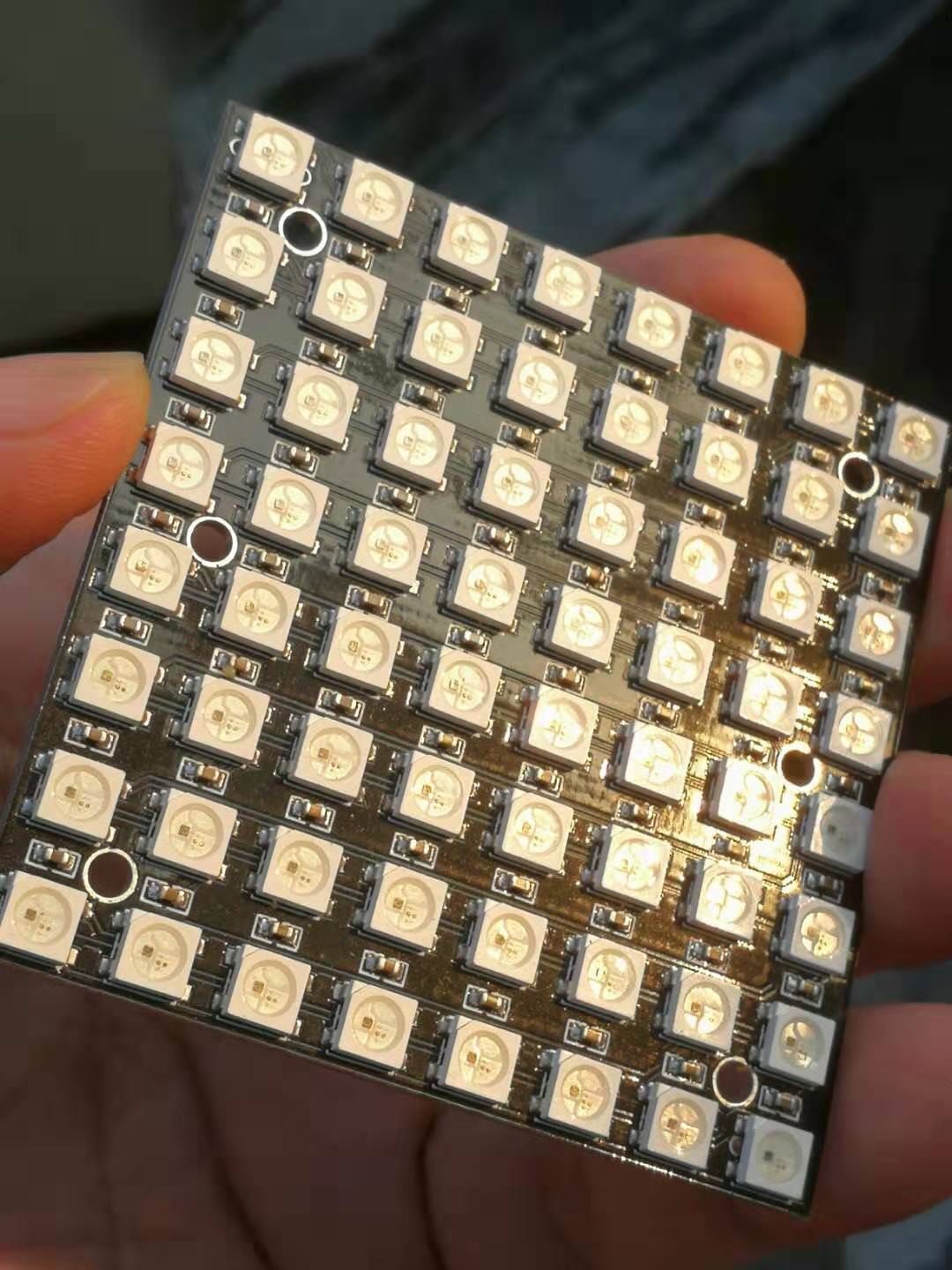
实验一百三十八:64位 WS2812B8*8 xRGB 5050 LED模块 ws2812s像素点阵屏
【Arduino】168种传感器模块系列实验(资料代码+仿真编程+图形编程)
实验一百三十八:64位 WS2812B8*8 xRGB 5050 LED模块 ws2812s像素点阵屏
项目三十:以纵向(垂直)方向在矩阵上滚动“Howdy eagler8”
实验开源代码
/*

【Arduino】168种传感器模块系列实验(资料代码+仿真编程+图形编程)

  实验一百三十八:64位 WS2812B8*8 xRGB 5050 LED模块 ws2812s像素点阵屏

 项目三十:以纵向(垂直)方向在矩阵上滚动“Howdy eagler8”

 实验接线

 Module  UNO

 VCC —— 3.3V

 GND —— GND

 DI —— D6

*/

#include <Adafruit_GFX.h>

#include <Adafruit_NeoMatrix.h>

#include <Adafruit_NeoPixel.h>

#ifndef PSTR

#define PSTR // Make Arduino Due happy

#endif

#define PIN 6

// MATRIX DECLARATION:

// Parameter 1 = width of NeoPixel matrix

// Parameter 2 = height of matrix

// Parameter 3 = pin number (most are valid)

// Parameter 4 = matrix layout flags, add together as needed:

//  NEO_MATRIX_TOP, NEO_MATRIX_BOTTOM, NEO_MATRIX_LEFT, NEO_MATRIX_RIGHT:

//   Position of the FIRST LED in the matrix; pick two, e.g.

//   NEO_MATRIX_TOP + NEO_MATRIX_LEFT for the top-left corner.

//  NEO_MATRIX_ROWS, NEO_MATRIX_COLUMNS: LEDs are arranged in horizontal

//   rows or in vertical columns, respectively; pick one or the other.

//  NEO_MATRIX_PROGRESSIVE, NEO_MATRIX_ZIGZAG: all rows/columns proceed

//   in the same order, or alternate lines reverse direction; pick one.

//  See example below for these values in action.

// Parameter 5 = pixel type flags, add together as needed:

//  NEO_KHZ800 800 KHz bitstream (most NeoPixel products w/WS2812 LEDs)

//  NEO_KHZ400 400 KHz (classic 'v1' (not v2) FLORA pixels, WS2811 drivers)

//  NEO_GRB   Pixels are wired for GRB bitstream (most NeoPixel products)

//  NEO_GRBW  Pixels are wired for GRBW bitstream (RGB+W NeoPixel products)

//  NEO_RGB   Pixels are wired for RGB bitstream (v1 FLORA pixels, not v2)

// Example for NeoPixel Shield. In this application we'd like to use it

// as a 5x8 tall matrix, with the USB port positioned at the top of the

// Arduino. When held that way, the first pixel is at the top right, and

// lines are arranged in columns, progressive order. The shield uses

// 800 KHz (v2) pixels that expect GRB color data.

Adafruit_NeoMatrix matrix = Adafruit_NeoMatrix(8, 8, PIN,

              NEO_MATRIX_TOP   + NEO_MATRIX_RIGHT +

              NEO_MATRIX_COLUMNS + NEO_MATRIX_PROGRESSIVE,

              NEO_GRB      + NEO_KHZ800);

int16_t x = matrix.width();

uint8_t color_index = 0;

char text[] = "Howdy eagler8";

int scroll_limit = sizeof(text) * 6; // each text character is 6 pixels wide

void setup() {

 matrix.begin();

 matrix.setTextWrap(false);

 matrix.setBrightness(33);

 matrix.setTextColor(matrix.Color(255, 0, 0)); // default color is red

}

void loop() {

 matrix.fillScreen(0);

 matrix.setCursor(x, 0);

 matrix.print(text);

 if (--x < -scroll_limit) {

  x = matrix.width();

  color_index = 0; // reset the rainbow color index

 }

 matrix.setTextColor(color_wheel(color_index));

 color_index += max(1, 256 / scroll_limit);

 matrix.show();

 delay(100);

}

uint16_t color_wheel(uint8_t pos) {

 pos = 255 - pos;

 if (pos < 85) {

  // return ((uint32_t)(255 - pos * 3) << 16) | ((uint32_t)(0) << 8) | (pos * 3);

  return matrix.Color((uint16_t)(255 - pos * 3), 0, (pos * 3));

 } else if (pos < 170) {

  pos -= 85;

  // return ((uint32_t)(0) << 16) | ((uint32_t)(pos * 3) << 8) | (255 - pos * 3);

  return matrix.Color(0, (uint32_t)(pos * 3), (255 - pos * 3));

 } else {

  pos -= 170;

  // return ((uint32_t)(pos * 3) << 16) | ((uint32_t)(255 - pos * 3) << 8) | (0);

  return matrix.Color((uint16_t)(pos * 3), (uint32_t)(255 - pos * 3), 0);

 }

}
【Arduino】168种传感器模块系列实验(资料代码+仿真编程+图形编程)
实验一百三十八:64位 WS2812B8*8 xRGB 5050 LED模块 ws2812s像素点阵屏
项目三十一:创建两个虚拟条带和一个物理条带的实例
实验开源代码
/*
  【Arduino】168种传感器模块系列实验(资料代码+图形编程+仿真编程)
  实验一百四十六:64位WS2812B 8*8 xRGB 5050 LED模块 ws2812s像素点阵屏
  项目三十一:创建两个虚拟条带和一个物理条带的实例
  实验接线
  Module    UNO
  VCC —— 3.3V
  GND —— GND
  DI  ——  D6
*/

#include <WS2812FX.h>

#define LED_PIN     6
#define LED_COUNT  64

// Create instances of two virtual strips and one physical strip.
// The animations will each run independently on the virtual strips,
// but the LED data will be merged and copied to the physical strip.
WS2812FX ws2812fx_v1 = WS2812FX(LED_COUNT, LED_PIN, NEO_GRB + NEO_KHZ800,1,1);
WS2812FX ws2812fx_v2 = WS2812FX(LED_COUNT, LED_PIN, NEO_GRB + NEO_KHZ800,1,1);
WS2812FX ws2812fx_p  = WS2812FX(LED_COUNT, LED_PIN, NEO_GRB + NEO_KHZ800,1,1);

void setup() {
  // Initialize the virtual strips
  ws2812fx_v1.init();
  ws2812fx_v1.setBrightness(34);
  ws2812fx_v1.setSegment(0, 0, LED_COUNT-1, FX_MODE_RAINBOW_CYCLE, BLACK, 1000, NO_OPTIONS);
  ws2812fx_v1.start();

  ws2812fx_v2.init();
  ws2812fx_v2.setBrightness(35);
  ws2812fx_v2.setSegment(0, 0, LED_COUNT-1, FX_MODE_LARSON_SCANNER, WHITE, 5000, NO_OPTIONS);
  ws2812fx_v2.start();

  // Initialize the physical strip. Since the physical strip gets
  // it's data from the virtual strips, no need to initialize segments.
  ws2812fx_p.init();

  // Config custom show() functions for the virtual strips, so their
  // pixel data gets merged and copied to the physical strip.
  ws2812fx_v1.setCustomShow(myCustomShow);
  ws2812fx_v2.setCustomShow(myCustomShow);
}

void loop() {
  // Run effects only on the virtual strips.
  ws2812fx_v1.service();
  ws2812fx_v2.service();
}

// The custom show() function blends and copies the virtual strips'
// data to the physical strip and then runs it's show() function.
void myCustomShow(void) {
  // get pointers to all the pixel data arrays
  uint8_t *pixels_v1 = ws2812fx_v1.getPixels();
  uint8_t *pixels_v2 = ws2812fx_v2.getPixels();
  uint8_t *pixels_p  = ws2812fx_p.getPixels();

  // blend the pixel data from the virtual strips and save it
  // to the physical strip
  for (int i=0; i < ws2812fx_p.getNumBytes(); i++) {
    pixels_p[i] = (pixels_v1[i] / 2) + (pixels_v2[i] / 2);
  }

  // Call the physical strip's show() function.
  // Note: the virtual strip's show() functions are never called.
  ws2812fx_p.Adafruit_NeoPixel::show();
}
【Arduino】168种传感器模块系列实验(资料代码+仿真编程+图形编程)
实验一百三十八:64位 WS2812B8*8 xRGB 5050 LED模块 ws2812s像素点阵屏
项目三十二:一个动画循环时增加闪烁计数器
实验开源代码
/*
  【Arduino】168种传感器模块系列实验(资料代码+图形编程+仿真编程)
  实验一百四十六:64位WS2812B 8*8 xRGB 5050 LED模块 ws2812s像素点阵屏
  项目三十二:一个动画循环时增加闪烁计数器
  实验接线
  Module    UNO
  VCC —— 3.3V
  GND —— GND
  DI  ——  D6
*/

#include <WS2812FX.h>

#define LED_PIN    6  // digital pin used to drive the LED strip
#define LED_COUNT 64  // number of LEDs on the strip

#define NUM_SEGMENTS        4  // maximum total number of segments that can be created
#define NUM_ACTIVE_SEGMENTS 2  // maximum number of segments that can be actively running

// create helper macros that define the start and end LEDs for each of our two segments
#define LOWER_SEG_RANGE 0, LED_COUNT/2 - 1
#define UPPER_SEG_RANGE LED_COUNT/2, LED_COUNT - 1

// example of the new WS2812FX constructor that adds parameters for the number of
// segments allowed and the number of active segments allowed.
WS2812FX ws2812fx = WS2812FX(LED_COUNT, LED_PIN, NEO_GRB + NEO_KHZ800, NUM_SEGMENTS, NUM_ACTIVE_SEGMENTS);

void setup() {
  Serial.begin(115200);

  ws2812fx.init();
  ws2812fx.setBrightness(32);

  // create two active segments
  ws2812fx.setSegment(0, LOWER_SEG_RANGE, FX_MODE_BLINK, YELLOW,             2000, NO_OPTIONS);
  ws2812fx.setSegment(1, UPPER_SEG_RANGE, FX_MODE_BLINK, COLORS(RED, GREEN), 2000, NO_OPTIONS);

  // create additional "idle" segments that will be activated later
  ws2812fx.setIdleSegment(2, LOWER_SEG_RANGE, FX_MODE_BLINK, CYAN,               2000, NO_OPTIONS);
  ws2812fx.setIdleSegment(3, UPPER_SEG_RANGE, FX_MODE_BLINK, COLORS(PINK, BLUE), 2000, NO_OPTIONS);

  ws2812fx.start();
}

void loop() {
  static unsigned long timer = millis();
  static unsigned int  blink_counter = 0;

  ws2812fx.service();

  /* the lower segment is updated based on a timer.
     the lower segment will change every 10 seconds
  */
  if(millis() > timer + 10000) {        // every 10 seconds...
    if(ws2812fx.isActiveSegment(0)) {   // if seg[0] is active, switch to seg[2]
      ws2812fx.swapActiveSegment(0, 2);
    } else {                            // else, switch to seg[0]
      ws2812fx.swapActiveSegment(2, 0);
    }
    timer = millis();
  }

  /* the upper segment is updated based on counting animation cycles. One "cycle" for the Blink
   *  effect is one on/off sequence. We'll change the upper segment every 5 blinks.
   */
  // increment the blink counter every time seg[1] or seg[3] complete an animation cycle
  if(ws2812fx.isCycle(1) || ws2812fx.isCycle(3)) {
    blink_counter++;
  }
  if(blink_counter >= 5) {                  // every 5 blinks...
    if(ws2812fx.isActiveSegment(1)) {       // if seg[1] active, switch to seg[3]
      ws2812fx.swapActiveSegment(1, 3);
    } else {                                // else, switch to seg[1]
      ws2812fx.swapActiveSegment(3, 1);
    }
    blink_counter = 0;
  }
}
【Arduino】168种传感器模块系列实验(资料代码+仿真编程+图形编程)
实验一百三十八:64位 WS2812B8*8 xRGB 5050 LED模块 ws2812s像素点阵屏
项目三十三:将一条 WS2812 LED 细分为动态三段
实验开源代码
/*
  【Arduino】168种传感器模块系列实验(资料代码+图形编程+仿真编程)
  实验一百四十六:64位WS2812B 8*8 xRGB 5050 LED模块 ws2812s像素点阵屏
  项目三十三:将一条 WS2812 LED 细分为动态三段
  实验接线
  Module    UNO
  VCC —— 3.3V
  GND —— GND
  DI  ——  D6
*/

#include <WS2812FX.h>

#define LED_PIN    6  // digital pin used to drive the LED strip
#define LED_COUNT 64  // number of LEDs on the strip

WS2812FX ws2812fx = WS2812FX(LED_COUNT, LED_PIN, NEO_GRB + NEO_KHZ800);

void setup() {
  Serial.begin(115200);

  ws2812fx.init();
  ws2812fx.setBrightness(28);

  // parameters: index, start, stop, mode, color, speed, reverse
  ws2812fx.setSegment(0,  0, 15, FX_MODE_BLINK, 0xFF0000, 1000, false); // segment 0 is leds 0 - 9
  ws2812fx.setSegment(1, 20, 39, FX_MODE_SCAN,  0x00FF00, 1000, false); // segment 1 is leds 10 - 19
  ws2812fx.setSegment(2, 40, 59, FX_MODE_COMET, 0x0000FF, 1000, true);  // segment 2 is leds 20 - 29

  ws2812fx.start();
}

void loop() {
  ws2812fx.service();
}
【Arduino】168种传感器模块系列实验(资料代码+仿真编程+图形编程)
实验一百三十八:64位 WS2812B8*8 xRGB 5050 LED模块 ws2812s像素点阵屏
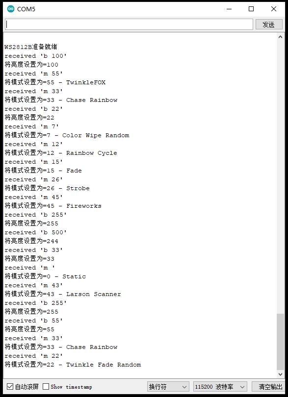
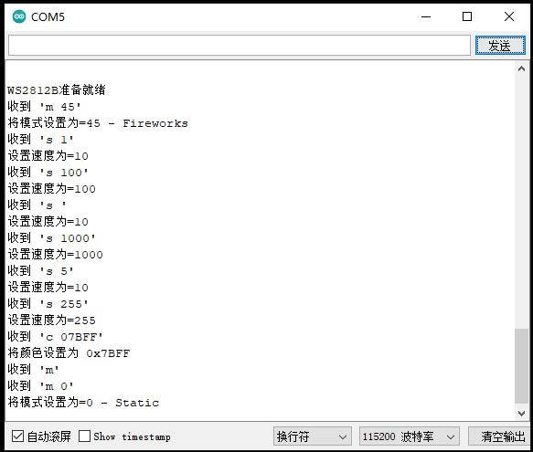
项目三十四:使用串行控制WS2812B模块的亮度、模式、速度及颜色
实验开源代码
/*
【Arduino】168种传感器模块系列实验(资料代码+图形编程+仿真编程)
实验一百四十六:64位WS2812B 8*8 xRGB 5050 LED模块 ws2812s像素点阵屏
项目三十四:使用串行控制WS2812B模块的亮度、模式、速度及颜色
实验接线
Module UNO
VCC —— 3.3V
GND —— GND
DI —— D6
*/
#include <WS2812FX.h>
#define LED_COUNT 64
#define LED_PIN 6
#define MAX_NUM_CHARS 16 // maximum number of characters read from the serial comm
// Parameter 1 = number of pixels in strip
// Parameter 2 = Arduino pin number (most are valid)
// Parameter 3 = pixel type flags, add together as needed:
// NEO_KHZ800 800 KHz bitstream (most NeoPixel products w/WS2812 LEDs)
// NEO_KHZ400 400 KHz (classic 'v1' (not v2) FLORA pixels, WS2811 drivers)
// NEO_GRB Pixels are wired for GRB bitstream (most NeoPixel products)
// NEO_RGB Pixels are wired for RGB bitstream (v1 FLORA pixels, not v2)
// NEO_RGBW Pixels are wired for RGBW bitstream (NeoPixel RGBW products)
WS2812FX ws2812fx = WS2812FX(LED_COUNT, LED_PIN, NEO_GRB + NEO_KHZ800);
char cmd[MAX_NUM_CHARS]; // char[] to store incoming serial commands
bool cmd_complete = false; // whether the command string is complete
void setup() {
Serial.begin(115200);
delay(200); // pause for serial comm to initialize
ws2812fx.init();
ws2812fx.setBrightness(33);
const uint32_t colors[] = { 0x400000, 0x004000, 0x000040 };
ws2812fx.setSegment(0, 0, LED_COUNT-1, FX_MODE_STATIC, colors, 1000, NO_OPTIONS);
// set the custom show function
ws2812fx.setCustomShow(myCustomShow);
ws2812fx.start();
printModes();
printUsage();
Serial.print(F("WS2812B准备就绪"));
}
void loop() {
ws2812fx.service();
recvChar(); // read serial comm
if(cmd_complete) {
process_command();
}
}
/*
* Checks received command and calls corresponding functions.
*/
void process_command() {
if (strncmp(cmd,"b ",2) == 0) {
uint8_t b = (uint8_t)atoi(cmd + 2);
ws2812fx.setBrightness(b);
Serial.print(F("将亮度设置为=")); Serial.println(ws2812fx.getBrightness());
}
if (strncmp(cmd,"m ",2) == 0) {
uint8_t m = (uint8_t)atoi(cmd + 2);
ws2812fx.setMode(m);
ws2812fx.resetSegmentRuntimes();
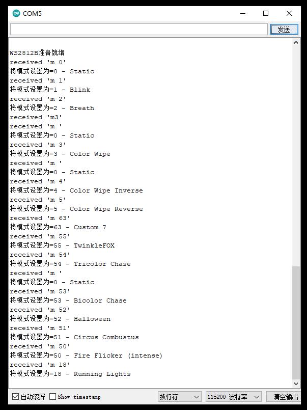
Serial.print(F("将模式设置为=")); Serial.print(ws2812fx.getMode());
Serial.print(" - "); Serial.println(ws2812fx.getModeName(ws2812fx.getMode()));
}
if (strncmp(cmd,"s ",2) == 0) {
uint16_t s = (uint16_t)atoi(cmd + 2);
ws2812fx.setSpeed(s);
Serial.print(F("设置速度为=")); Serial.println(ws2812fx.getSpeed());
}
if (strncmp(cmd,"c ",2) == 0) {
uint32_t c = (uint32_t)strtoul(cmd + 2, NULL, 16);
ws2812fx.setColor(c);
Serial.print(F("将颜色设置为 0x")); Serial.println(ws2812fx.getColor(), HEX);
}
cmd[0] = '\0'; // reset the commandstring
cmd_complete = false; // reset command complete
}
/*
* Prints a usage menu.
*/
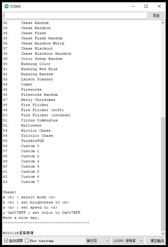
const char usageText[] PROGMEM = R"=====(
Usage:
m <n> : select mode <n>
b <n> : set brightness to <n>
s <n> : set speed to <n>
c 0x007BFF : set color to 0x007BFF
Have a nice day.
~~~~~~~~~~~~~~~~~~~~~~~~~~~~~~~~~~~~~~
)=====";
void printUsage() {
Serial.println((const __FlashStringHelper *)usageText);
}
/*
* Prints all available WS2812FX modes/effects
*/
void printModes() {
Serial.println(F("支持以下模式:\r\n"));
for(int i=0; i < ws2812fx.getModeCount(); i++) {
Serial.print(i); Serial.print('\t'); Serial.println(ws2812fx.getModeName(i));
}
}
/*
* Reads new input from serial to cmd string. Command is completed on \n
*/
void recvChar(void) {
static byte index = 0;
while (Serial.available() > 0 && cmd_complete == false) {
char rc = Serial.read();
if (rc != '\n') {
if(index < MAX_NUM_CHARS) cmd[index++] = rc;
} else {
cmd[index] = '\0'; // terminate the string
index = 0;
cmd_complete = true;
Serial.print("received '"); Serial.print(cmd); Serial.println("'");
}
}
}
#define MAX_CURRENT 500 // maximum allowed current draw for the entire strip (mA)
#define QUIESCENT_CURRENT 56 // current draw for the entire strip with all LEDs off (mA)
#define INCREMENTAL_CURRENT 40 // increase in current for each intensity step per RGB color (uA)
#define MAX_INTENSITY_SUM ((MAX_CURRENT - QUIESCENT_CURRENT) * 1000) / INCREMENTAL_CURRENT
void myCustomShow(void) {
static uint32_t lastSum = 0;
uint32_t intensitySum = ws2812fx.intensitySum(); // get intensity sum for all LEDs
if(lastSum != intensitySum) { // if intesity sum has changed, check if it exceeds the maximum
if(intensitySum > MAX_INTENSITY_SUM) { // exceeded the maximum, so calculate a new brightness setting
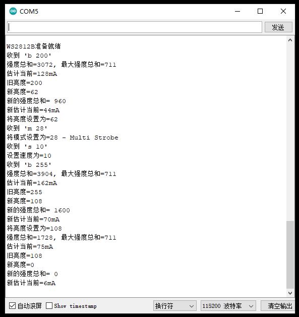
Serial.print("强度总和="); Serial.print(intensitySum);
Serial.print(", 最大强度总和="); Serial.println(MAX_INTENSITY_SUM);
uint32_t estimatedCurrent = ((intensitySum * INCREMENTAL_CURRENT) / 1000) + QUIESCENT_CURRENT;
Serial.print("估计当前="); Serial.print(estimatedCurrent); Serial.println("mA");
uint8_t oldBrightness = ws2812fx.Adafruit_NeoPixel::getBrightness();
Serial.print("旧亮度="); Serial.println(oldBrightness);
uint8_t scaleFactor = (MAX_INTENSITY_SUM * 256) / intensitySum; // brightness scaling factor
uint8_t newBrightness = constrain(((oldBrightness * scaleFactor) / 256), BRIGHTNESS_MIN, BRIGHTNESS_MAX);
Serial.print("新亮度="); Serial.println(newBrightness);
// call the Adafruit_Neopixel::setBrightness() function, because the WS2812FX::setBrightness() function calls show(), which we don't want.
ws2812fx.Adafruit_NeoPixel::setBrightness(newBrightness);
// optionally, for verification, recalculate the intensity sum and current estimate
intensitySum = ws2812fx.intensitySum();
Serial.print("新的强度总和= "); Serial.println(intensitySum);
estimatedCurrent = ((intensitySum * INCREMENTAL_CURRENT) / 1000) + QUIESCENT_CURRENT;
Serial.print("新估计当前="); Serial.print(estimatedCurrent); Serial.println("mA");
}
lastSum = intensitySum;
}
ws2812fx.Adafruit_NeoPixel::show();
}实验串口返回情况
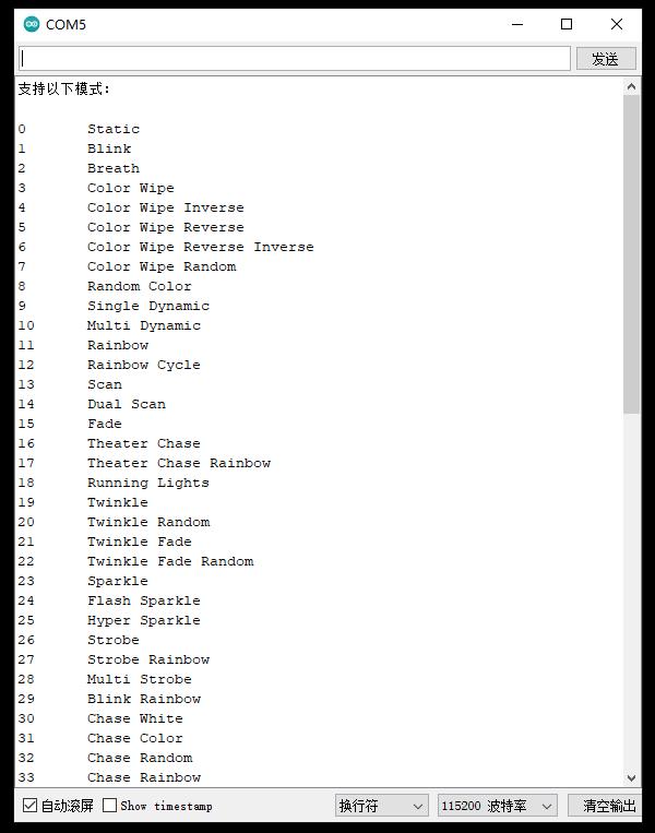
测试各种模式
加上自定义,一共63种可选的模式
0 静态
1 闪烁
2 呼吸
3 颜色测试
4 色测试反转
5 色擦拭反转
6 色擦拭反向反向
7色擦随机
8 随机颜色
9 单动态
10 多动态
11 彩虹
12 彩虹循环
13 扫描
14 双扫描
15 淡入淡出
16 剧院追逐
17 剧院追逐彩虹
18个行车灯
19 闪烁
20 闪烁随机
21 闪烁淡入淡出
22 闪烁淡入淡出随机
23 闪耀
24 闪光闪光
25 超闪耀
26 频闪
27频闪彩虹
28 多频闪
29 闪烁彩虹
30 追白
31 追逐色
32 追逐随机
33 追逐彩虹
34 追逐闪光
35 追闪随机
36追逐彩虹白
37 大通停电
38 追逐停电彩虹
39色扫随机
40 跑步色
41奔跑红蓝
42 随机运行
43 拉森扫描仪
44 彗星
45 烟花
46烟花随机
47 圣诞快乐
48火焰闪烁
49火闪烁(软)
50火焰闪烁(强烈)
51 马戏团康布斯图斯
52 万圣节
53 双色追逐
54 三色追逐
55闪烁狐狸
56 自定义 0
57 自定义 1
58 自定义 2
59 自定义 3
60 自定义 4
61 自定义 5
62 自定义 6
63 自定义 7
尝试串口调整亮度,0-255
尝试串口设置速度和颜色
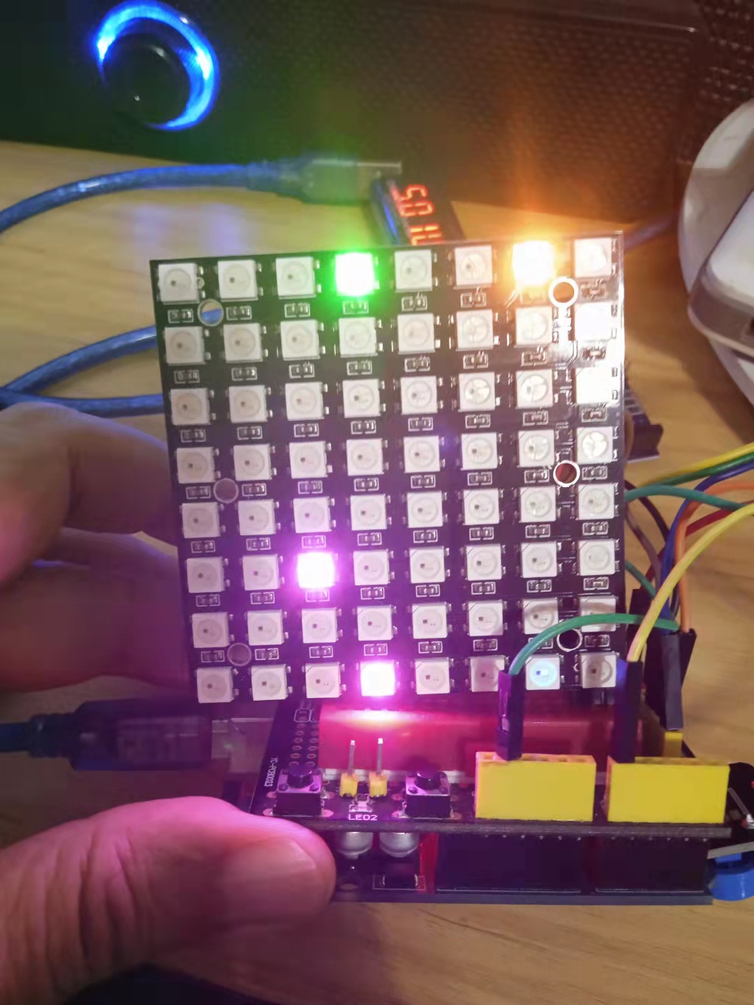
Arduino实验场景图
测试总电流自动控制功能,这里设为100毫安,只要超过会自动降下来
WS2812FX库最简单的形式,这是让您入门的代码!
/*

【Arduino】168种传感器模块系列实验(资料代码+仿真编程+图形编程)

  实验一百三十八:64位 WS2812B8*8 xRGB 5050 LED模块 ws2812s像素点阵屏

 项目三十五:WS2812FX库最简单的形式

*/

#include <WS2812FX.h> //导入库

#define LED_COUNT 64 //WS2812B LED数量

#define LED_PIN  6 //WS2812B LED接脚

WS2812FX ws2812fx = WS2812FX(LED_COUNT, LED_PIN, NEO_GRB + NEO_KHZ800);

void setup() {

 ws2812fx.init(); //初始化

 ws2812fx.setBrightness(255); //设置亮度(0-255),可以控制总电流(重要!)

 ws2812fx.setSpeed(200); // 设置速度

 ws2812fx.setMode(FX_MODE_FIREWORKS_RANDOM);// 设置模式(内置63种模式)

 ws2812fx.start(); //启动

}

void loop() {

 ws2812fx.service(); //循环运行

}

 他的勋章
他的勋章

9mm2023.08.16
666