 返回首页
返回首页
 回到顶部
回到顶部
在手腕上总是戴着时钟的时候,无论是手腕上的手表还是智能手机,Arduino Uno/Nano 都有点沉闷。否则,您将本文中的 NTP 服务器同步设备放在外部,这些设备通过您的 Internet 连接始终在线。
我的一个朋友出于个人原因拒绝在他的卧室里使用带有 WiFi 连接的设备,所以我让 Arduino 配备了一个单独的时钟。
选择合适的产品
我很惊讶,甚至 Adafruit 也有这么多不同的产品可供选择:取决于所需的张力,以及不同的精度!在这里,我决定使用两种产品:更便宜的 DS1307 和可能更精确的 DS3231。
需要明确的是:这两种产品都可以用于这个时钟。要使用DS1307,请注意正确的PIN分配和温度显示选项的限制: 在displayTemp()上注“//”;loop () 中的函数。
调整程序
我去找程序,发现了另一个成员的东西。我重新构建并适应了这个程序,但保留了捷克语的评论并添加了英语评论。
广告应该尽可能大,所以我决定做一个 7 段的广告:毕竟,我只想把时间放在心上。
我在查看草图时遇到的下一个积极的惊喜是:在这里,DS3231 提供了使用温度的选项,而 DS1307 除了不准确之外还缺少温度。
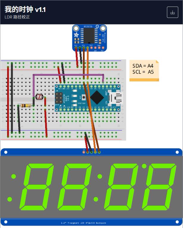
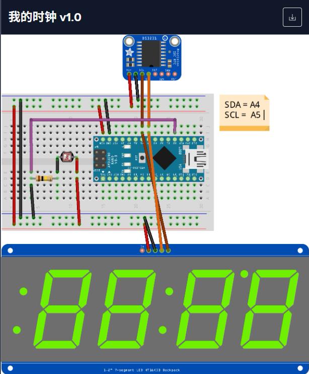
初始化时钟
如果您有 CR1220 纽扣电池,您可以按照 Adafruit 的简短教程设置时钟进行作。总之,时间不是从 Internet 下载的,而是随着时间的推移从本地 PC 下载的。上传时间戳将传输到计时器。
功能
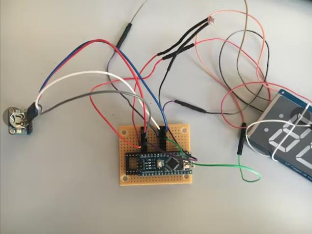
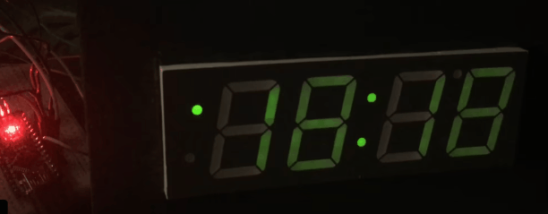
之后,我将 LED 矩阵添加到电路中以进行时间和温度输出。时间和温度的变化周期可以通过变量设置。
特别是,程序中详细描述了对 LED 矩阵上单个 - 闪烁 - 点和数字的控制是如何工作的和控制的。
在这里,我参考了更多 Adafruit 来源。
程序通过根据环境光调整夏/冬时间和 LED 矩阵的亮度(夜间显示屏应比白天暗)来完善。
在视频中,您当然注意到了时间和温度的变化。你注意了图片左边的点吗?这会根据秒数改变其位置(向上或向下)。
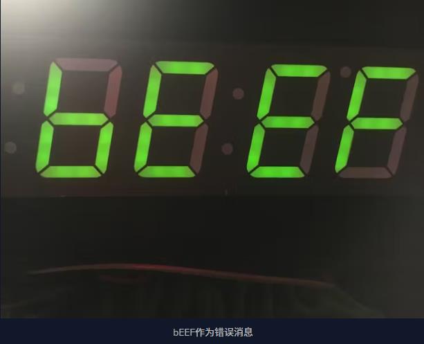
如果您知道如何在时钟出现故障时在 LED 矩阵上发出“ERR”,请给我反馈。此刻会出现“bEEF”。
扩张
警报或警报时间也尚未集成。
也可能通过蓝牙模块和 Blynk 进行扩展。
更新:
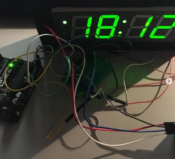
从面包板到打孔卡永久投注的转移今天已经完成。
项目代码
// MyClock v1.1
// Ingo Lohs
// Hardware: tested with Arduino Uno and Arduino Nano (ATmega328P [Old Bootloader]) by using Arduino IDE v1.8.8

// Change v1.0 > v1.1
// dayOfWeek == 1 anstatt 7 abgeändert in displayTime() zur korrekten Ermittlung des Sonntages für die Zeitumstellung

/* Theory for the Matrix ht16k33
The easiest is to just call print - just like you do with Serial
print(variable,HEX) - this will print a hexidecimal number, from 0000 up to FFFF
print(variable,DEC) or
print(variable) - this will print a decimal integer, from 0000 up to 9999

If you need more control, you can call writeDigitNum(location, number) - this will write the number (0-9) to a single location.
Location #0 is all the way to the left, location #2 is the colon dots so you probably want to skip it, location #4 is all the way to the right.

To control the colon and decimal points, use the writeDigitRaw(location, bitmap) function.
(Note that both dots of the center colon are wired together internal to the display, so it is not possible to address them separately.)

Specify 2 for the location and the bits are mapped as follows:
0x02 - center colon (both dots)
0x04 - left colon - lower dot
0x08 - left colon - upper dot
0x10 - decimal point

If you want a decimal point, call writeDigitNum(location, number, true) which will paint the decimal point.
To draw the colon, use drawColon(true or false)

If you want full control of the segments in all digits, you can call writeDigitRaw(location,bitmask) to draw a raw 8-bit mask (as stored in a uint8_t) to any location.

All the drawing routines only change the display memory kept by the Arduino. Don't forget to call writeDisplay() after drawing to 'save' the memory out to the matrix via I2C.

Source: https://www.mouser.com/ds/2/737/adafruit-led-backpack-932846.pdf
*/

#include <Wire.h> // Enable this line if using Arduino Uno, Mega, etc.
#include <Adafruit_GFX.h>
#include "Adafruit_LEDBackpack.h"

#define DS3231_I2C_ADDRESS 0x68

int ldr_sensor = A0;            // LDR Photoresistor with 100k Ohm to GND, other leg 5V
int ldr_value = 0;              // LDR value - var store value
int brightness_matrix;          // LED Matrix brightness - var store value
int threshold_brightness = 400; // Threshold
int blinkrate_value = 0;        // LED Matrix blink rate
int delay_matrix_time = 20;     // how long display time (20 sec)
int delay_matrix_temp = 2000;   // how long display temp (2 sec)
int blinky_dot = 2;             // blinks nothing - on the left side 2 single dots

Adafruit_7segment matrix = Adafruit_7segment();

byte decToBcd(byte val){
return ( (val/10*16) + (val%10) );
}

byte bcdToDec(byte val){
return ( (val/16*10) + (val%16) );
}

void setup() {
  Serial.begin(9600);
  Wire.begin();
  matrix.begin(0x70);
}

void loop() {
    lightBrightness(); // Matrix-Brightness Justierung
    matrixBlinkrate(); // Mattrix-Blinkrate Jusitierung
    displayTime();     // display the real-time clock data
    displayTemp();     // display the temperature
}

void lightBrightness() {
// setBrightness(brighness) - will let you change the overall brightness of the entire display. 0 is least bright, 15 is brightest and is what is initialized by the display when you start
    ldr_value = analogRead(ldr_sensor);
    Serial.print("LDR: ");
    Serial.println(ldr_value);
    if (ldr_value <= threshold_brightness) { // measurement of brightness vs Threshold
      brightness_matrix = 0; // bright at daylight
    }
    else {
      brightness_matrix = 15; // dark at night
    }
}

void matrixBlinkrate() {
// blinkRate(rate) - You can blink the entire display. 0 is no blinking. 1, 2 or 3 is for display blinking.
 matrix.blinkRate(blinkrate_value);
}

void displayTime(){
matrix.setBrightness(brightness_matrix);
matrix.clear();

// how long display time on matrix in seconds
for (uint16_t i = 0; i < delay_matrix_time; i++) {
  byte second, minute, hour, dayOfWeek, dayOfMonth, month, year;
  getDateDs3231(&second, &minute, &hour, &dayOfWeek, &dayOfMonth, &month, &year);
    byte se = second;
    byte mi = minute;
    byte ho = hour;
    byte we = dayOfWeek;
    byte dm = dayOfMonth;
    byte mo = month;
    byte ye = year;

    // změna času na letní - poslední neděle v březnu ve 2 hodiny
    // >> Change to summer time - last Sunday in March at 2 o'clock
    if ((dayOfWeek == 1) && (dayOfMonth >= 25)&& (month == 3) && (hour == 2)) {
      // nastavení hodin na 3 hodinu
      // set the clock to 3 hours
      setDS3231time(se,mi,3,we,dm,mo,ye);
    }

    // změna času na zimní
    // >> Change to winter time
    if ((dayOfWeek == 1) && (dayOfMonth >= 25) && (month == 10) && (hour == 1)&& (year != 1)) {

      // rok použit jako indikace, že bylo léto
      // year used as an indication that it was summer
      setDS3231time(se,mi,ho,we,dm,mo,1);
    }

    if ((dayOfWeek == 1) && (dayOfMonth >= 25) && (month == 10) && (hour == 3) &&(year == 1)) {
      // nastavení hodin na 2 hodinu a příznak na 0
      // set the clock to 2 hours and flag year to 0
      setDS3231time(se,mi,2,we,dm,mo,0);
    }

     /*
      Specify 2 for the location and the bits are mapped as follows:
      0x02 - center colon (both dots)
      0x04 - left colon - lower dot
      0x08 - left colon - upper dot
      0x10 - decimal point
     */

     /* location #2 controls also the left 2 single points like this (=blinky_dot):
      2 = blinks nothing
      3 = blinks nothing
      4 = blinks top left (single upper dot)
      5 = blinks top left (single upper dot)
      6 = blinks top left (single upper dot) + both Colon in mid
      7 = blinks top left (single upper dot) + both Colon in mid
      8 = blinks bottom left (single lower dot)
      9 = blinks bottom left (single lower dot)
     10 = blinks bottom left (single lower dot) + both Colon in mid
     11 = blinks bottom left (single lower dot) + both Colon in mid
     12 = blinks both Colon (both single dots left) without both Colon in mid
     */

    // format hours: _0:mm
    if (hour > 9) {
    matrix.writeDigitNum(0, (hour / 10), false);
    matrix.writeDigitNum(1, (hour % 10), false);    // this will write the number (0-9) to a single location by using modulo https://www.arduino.cc/reference/en/language/structure/arithmetic-operators/modulo/
    } else {
    matrix.writeDigitNum(1, hour, false);
    }

      // matrix.drawColon(true);                    // both Colon in mid active: in case you want not blink the dots left you can activate the both Colon here

    // give seconds a chance to show at left location dots
    if (se <= 30) {
      blinky_dot = 10; // blinks bottom left (single lower dot) + both Colon in mid
    } else if (se > 30) {
      blinky_dot = 6;   // blinks top left (single upper dot) + both Colon in mid
    }
      matrix.writeDigitRaw(2, blinky_dot);

      matrix.writeDigitNum(3, (minute / 10), false);
      matrix.writeDigitNum(4, (minute % 10), false);

      matrix.writeDisplay();

      // blinky double dots for half seconds
      delay(500);
      matrix.drawColon(false);
      matrix.writeDisplay();
      delay(500);
  }
}

void displayTemp(){
matrix.setBrightness(brightness_matrix);
matrix.clear();

  byte temp = get3231Temp();
  int abs_temp = abs(temp);                                           // absolute number of a value

  matrix.writeDigitNum(1,(abs_temp % 10), false);                     // position 1, value 9, show decimal)

  if (temp < 0)    matrix.writeDigitRaw(0,64);
  if (temp <= -10) matrix.writeDigitRaw(2,12);                        // and if the temperature is negative, we plot the minus sign to first place.
  if (temp >= 10)  matrix.writeDigitNum(0, (abs_temp/10), false);     // position 0, value 1, show decimal)
  if (temp <= -10) matrix.writeDigitNum(0, (abs_temp/10), false);     // position 0, value 1, show decimal)
  // matrix.writeDigitRaw(2,0x10);                                    // decimal dot

  matrix.writeDigitRaw(3,99);                                         // 99 = "°"
  matrix.writeDigitRaw(4,57);                                         // 57 = "C"
  matrix.writeDisplay();

  // displays temperature values on the serial line
  // zobrazí hodnoty teploty na seriove lince
  Serial.print("Temperatur in C: ");
  Serial.println(get3231Temp());                                      // +/- 3 Grad Celsius

  // how long display temp on matrix in seconds
  delay(delay_matrix_temp);
}

void setDS3231time(byte second, byte minute, byte hour, byte dayOfWeek, byte dayOfMonth, byte month, byte year){
    // set time and date data to DS3231
    Wire.beginTransmission(DS3231_I2C_ADDRESS);
    Wire.write(0);                    // set next input to start at the seconds register
    Wire.write(decToBcd(second));     // set seconds
    Wire.write(decToBcd(minute));     // set minutes
    Wire.write(decToBcd(hour));       // set hours
    Wire.write(decToBcd(dayOfWeek));  // set day of week (1=Sunday, 7=Saturday)
    Wire.write(decToBcd(dayOfMonth)); // set date (1 to 31)
    Wire.write(decToBcd(month));      // set month
    Wire.write(decToBcd(year));       // set year (0 to 99)
    Wire.endTransmission();
}

void getDateDs3231
(byte *second,
 byte *minute,
 byte *hour,
 byte *dayOfWeek,
 byte *dayOfMonth,
 byte *month,
 byte *year)
{
    Wire.beginTransmission(DS3231_I2C_ADDRESS);
    Wire.write(0);
    Wire.endTransmission();
    Wire.requestFrom(DS3231_I2C_ADDRESS, 7);
    *second = bcdToDec(Wire.read() & 0x7f);
    *minute = bcdToDec(Wire.read());
    *hour = bcdToDec(Wire.read() & 0x3f);
    *dayOfWeek = bcdToDec(Wire.read());
    *dayOfMonth = bcdToDec(Wire.read());
    *month = bcdToDec(Wire.read());
    *year = bcdToDec(Wire.read());
}

float get3231Temp(){
  byte tMSB, tLSB;
  float temp3231;

    Wire.beginTransmission(DS3231_I2C_ADDRESS);
    Wire.write(0x11);
    Wire.endTransmission();
    Wire.requestFrom(DS3231_I2C_ADDRESS, 2);

    if (Wire.available()) {
      tMSB = Wire.read();                 // 2's complement int portion
      tLSB = Wire.read();                 // fraction portion
      temp3231 = (tMSB & B01111111);      // do 2's math on Tmsb
      temp3231 += ( (tLSB >> 6) * 0.25 ); // only care about bits 7 & 8

      return temp3231;
    }
    else {
    // oh no, no data!
      Serial.println("DS3231 Sensor Error - cant read temperature");
      matrix.print(0xBEEF, HEX); // inform the user with BEEF
      matrix.writeDisplay();
      delay(5000);
    }
}
【Arduino 动手做】采用Arduino Nano + DS3231 + LDR的7段时钟
项目链接:https://www.hackster.io/ingo-lohs/7-segment-clock-with-arduino-nano-ds3231-ldr-286f4b
项目作者:英戈·洛斯
项目视频 :https://vimeo.com/310608873?fl=pl&fe=ti&pgroup=plv
项目代码:
https://www.hackster.io/code_files/228037/download
https://www.hackster.io/code_files/231657/download


 他的勋章
他的勋章

评论