 返回首页
返回首页
 回到顶部
回到顶部
自初始版本以来,我更新了 LiDAR 代码以提高性能!请参阅此 Instructable 的第 8 步,以获取视频和更新的文件。该视频还展示了更多的测试示例,并试图解释 LiDAR 性能的更多细节。非常感谢您到目前为止的反馈和评论,阅读它们很有趣~
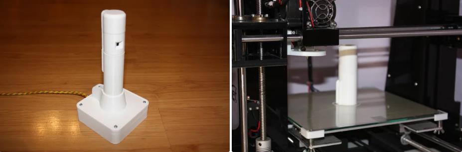
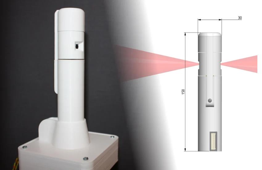
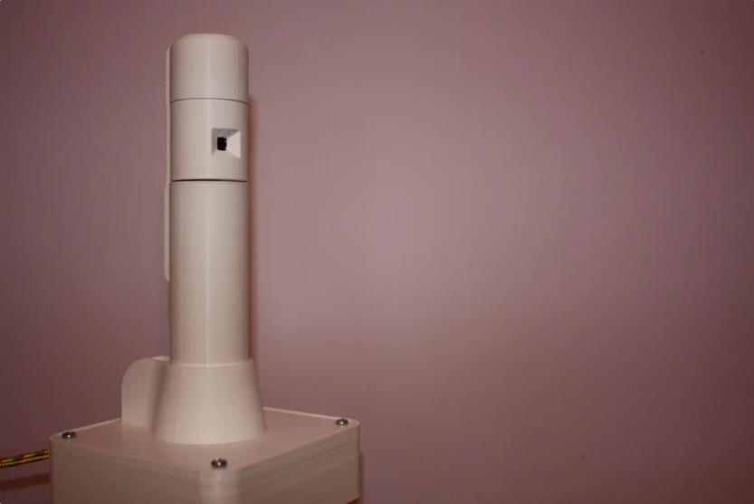
在这个 Instructable 中,我们将构建一个由 Arduino 提供支持的廉价旋转 LiDAR 传感器。它的制造成本不到 30 英镑(40 美元),直径仅为 30 毫米(1.18 英寸)。它使用两个彼此截然相反的传感器,使扫描速度翻倍,适合安装在小型机器人的顶部。所有部件均经过 3D 打印,也适用于小型 3D 打印机。请观看视频摘要,了解构建的分步过程以及测试视频片段!然后,Instructables 指南应该为您提供自己重现项目所需的所有详细信息。
安全性:使用热 3D 打印机和烙铁会带来一些风险来源,但除此之外,整个过程中都使用低电压,并且 VL53L0X 传感器不会产生对眼睛有害的激光。如果合适,鼓励父母监督,但请小心运动并在需要时使用护目镜。
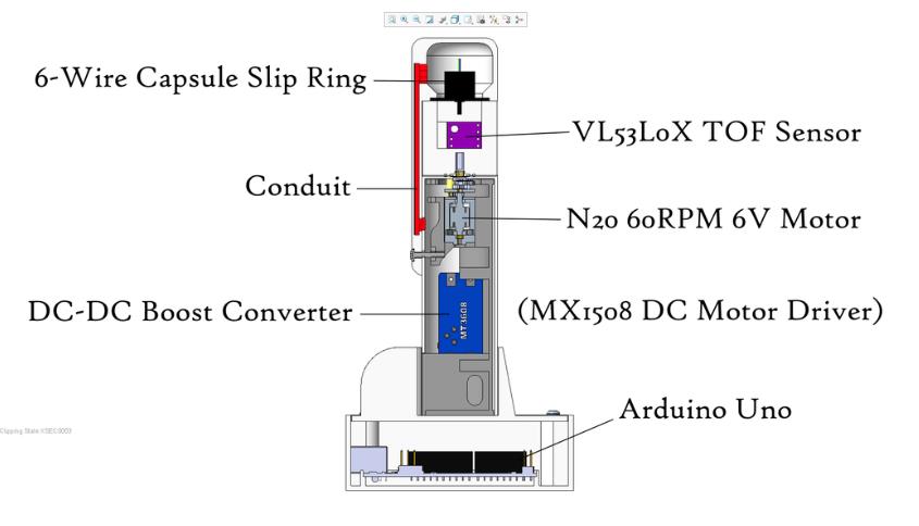
LiDAR “灯塔”
2 个 VL53L0X TOF 测距传感器
MT3608 DC-DC 升压转换器
MX1508 直流电机驱动器
8 路 Molex PCB 连接器(母头)
N20 6V 电机(微型金属减速电机)- 60 RPM
6 线胶囊滑环
M2.5x12 螺丝 + M2.5 螺母
测试基站“Lighthouse Keeper”
Arduino Uno
USB 数据线
5V 1A 壁式插头
8 路 Molex PCB 连接器(公头)
7 个接头引脚
4 个 M3x12 螺丝 + 4 个 M3 螺母
消耗品
无铅焊料
热缩管(不是必需的,但最好 - 可以用电工胶带代替)
电气绝缘胶带
胶水(CA 强力胶就合适了)
用于 3D 打印机的 PLA 线材
软件
一台 PC,正在运行;
Arduino IDE
处理 - 一个图形库,我们将使用它来在 PC 上显示传感器输出
CAD 软件,例如 Autodesk Inventor - 如果您想修改 3D 打印部件
切片软件 - 用于为 3D 打印机设置文件
工具
3D 打印机
螺丝刀
烙铁、剥线钳、侧刀
工艺刀、锉刀
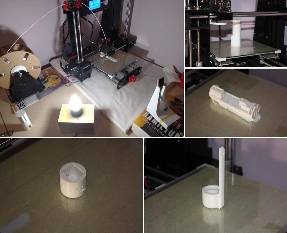
塑料(和 3D 打印)使这个项目成为可能!我们使用的塑料是 PLA(聚酰亚胺,一种常用于 3D 打印细丝的淀粉衍生塑料)。FDM(熔融沉积建模,描述大多数业余 3D 打印机中使用的细丝型打印的奇特方式)是一种能够创建高质量和低成本组件的低成本方式,没有它,我们就无法做到这一点!不可否认,以另一种方式制造这些组件会更慢、更棘手且更昂贵。我使用的 3D 打印机是 Anet A6,这是一台低成本的机器,但足以完成像这样的项目。
设计
我设计中的关键驱动因素是:
低成本 - 组件的总价应尽可能低。
最小尺寸 - 专注于保持尽可能小的尺寸。
性能 - 近乎 360° 的覆盖和快速的扫描速度。
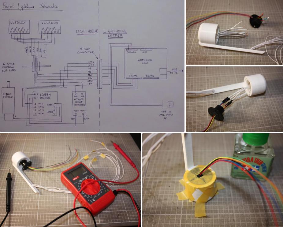
整个过程中使用了基本且广泛可用的组件,并且由于省略了任何形式的编码器,成本降至最低。这将用于测量扫描头的旋转角度。相反,一个柱子位于传感器的扫描弧内;由此,可以通过记录传感器何时检测到柱子的存在来计算头部的旋转角度,然后计算转速,从而计算距离测量之间的角度间隔。
“滑环”是一种允许通过旋转接口进行电气连接的组件,我们使用 6 线胶囊滑环将两个传感器的连接向下连接到激光雷达塔的主体中。通过将滑环重新定位到旋转头上方,然后使用支柱将电线向下布线到塔中,可以创建一个非常简单的布局,它使用少量组件。
为什么选择 LiDAR?
自从我研究了一些基本的轮式机器人以来,我一直想制作一个旋转距离传感器。那时我没有能力设计一个,但在过去的几个月里,我越来越多地玩弄这个设计,并决定最终实现它!
以前,我使用基本的固定超声波 (HC-SR04) 和 IR (Sharp 系列) 传感器进行距离传感,但以前从未使用过旋转传感器。市售的旋转 LiDAR 传感器对我来说相当昂贵,所以我想尝试以非常低的成本开发一个基本的传感器。如果成功,我计划使用这个传感器来导航小型机器人,以及房间映射。我选择使用的 VL53L0X 传感器的波长为 940nm,人眼看不见,但智能手机相机会显示明亮的闪光!
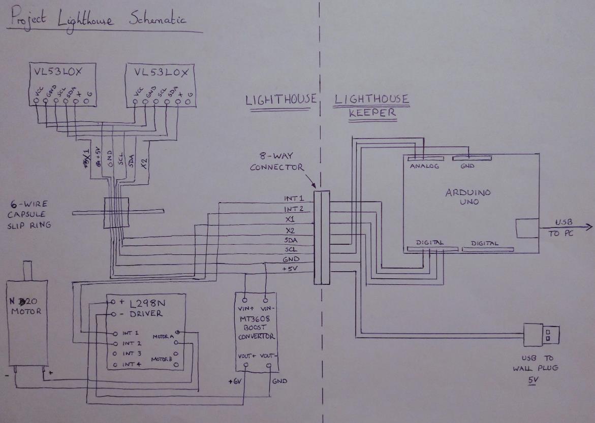
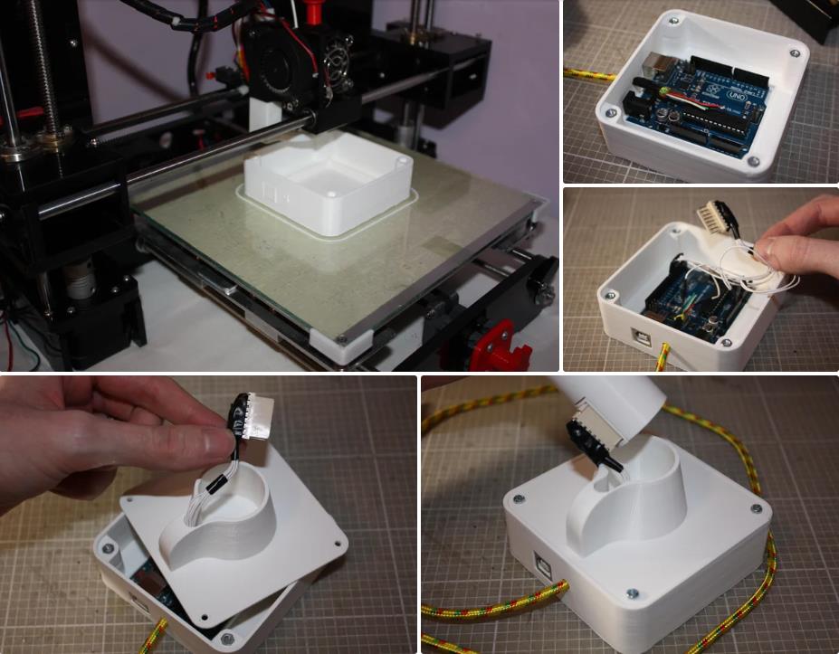
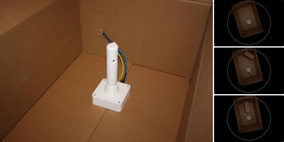
LiDAR 被设计为安装在任何类型的小型机器人上,但为了测试,我设计了这个小型基站。它包含一个 Arduino Uno,一个 5V 壁式电源的接口,以及一个用于连接“Lighthouse”的 8 路公 Molex 连接器。它代表了通用机器人的电源和控制接口,为了进行测试,我得以开发 LiDAR 的代码并测试功能。
它分两部分印刷,一个底座和一个盖子,它们用 4 个 M3x12 螺栓和螺母连接。Arduino 通过摩擦方式安装在底座中。我使用 1m 长的 USB 电缆从 5V 1A 壁式插头供电。切开这根线,然后选择红色 5V 和黑色接地线,如图所示。Arduino 将通过 USB 到 PC 连接获取电源,但将 Arduino 的 GND 引脚连接到墙上插头的输入接地线非常重要。
将其他线路焊接到 Molex 连接器上,并如图所示用绝缘胶带包裹。确保您已仔细检查短路,并确保基站连接器上的引脚与灯塔上的引脚匹配!
总的来说,这是一个非常有趣的项目,令人欣慰的是,初步结果非常有希望。使用它可以开发更多内容,但令人兴奋的是,它已经能够对其环境进行简单的映射。
如果我要设计另一个传感器,我想把一些事情做得更好一些:
寻找减少读取传感器所需时间间隔的方法。在初始版本中,执行一个读取周期需要 100 毫秒以上。在代码更新之后(请参阅第 8 步),我设法将其减少到 57 毫秒,从而允许每次旋转记录更多数据。我认为 VL53L0X 现在是主要的限制因素,而不是代码、Arduino 或 Project Lighthouse 硬件的其余部分,因为传感器被限制为 20 毫秒作为最快的读取时间,而这个项目使用了其中的两个。我能想到的进一步加速这一过程的唯一方法可能是让两个传感器由单独的 Arduino (Pro Minis?) 独立控制,然后将他们的数据传递给中央控制器,这样他们就可以并行记录他们的数据,而不是一个接一个地记录每个传感器......
更复杂的数据记录。我认为可以通过在每次连续旋转的记录之间添加一个小的时间延迟来构建更完整的周围环境图 - 这将具有将每次旋转的数据集偏移几度的效果。在多次旋转之后,这可能会产生比我当前记录数据的少量角度更密集的数据的效果。
我知道目前代码没有考虑第 1 个和第 2 个 ToF 传感器的读数之间发生的旋转 - 这是一个故意简化的,但将是一个有趣的方面,可以尝试在代码中考虑。


项目代码
//Update 1.1 of program, released on Instructables on 13/02/21.
//This update requires no modifications to the hardware, but makes improvements to the code.
//Please see the corresponding video!

#include <Wire.h> //These are the necessary libraries used in the program
#include "Adafruit_VL53L0X.h"

//The following adafruit tutorial is recommended to learn more about the VL53L0X sensors:
//https://learn.adafruit.com/adafruit-vl53l0x-micro-lidar-distance-sensor-breakout/arduino-code

#define LOX1_ADDRESS 0x30 //The first intended 12C address
#define LOX2_ADDRESS 0x31 //The second intended 12C address

#define SHT_LOX1 11 //Arduino pin for the X wire of the first VL53L0X
#define SHT_LOX2 12 //Arduino pin for the X wire of the second VL53L0X

Adafruit_VL53L0X lox1 = Adafruit_VL53L0X(); //Setting up the sensors using the adafruit library
Adafruit_VL53L0X lox2 = Adafruit_VL53L0X();

VL53L0X_RangingMeasurementData_t measure1;
VL53L0X_RangingMeasurementData_t measure2;

const int FwdPin = 10;  //Forward Motor Pin
const int BwdPin = 9; //Backward Motor Pin
int MaxSpd = 60;  //Top speed (0-255) - I found that 60 is a good level to test
boolean DirFlag = true; //Flag for direction

int sensor1, sensor2; //Creates int type variable for sensors
int sum = 0;
int counter;
float xangle = 0;
int xinterval = 0;
int heading = 0;
int marker = 0;

void setup()
{
  delay(1000);
  Serial.begin(115200); //Sets baud rate for Serial. Make sure identical rate is selected in Serial Monitor/Processing
  while (! Serial) {  //Wait until serial port opens for native USB devices
    delay(1);
  }
  pinMode(SHT_LOX1, OUTPUT);
  pinMode(SHT_LOX2, OUTPUT);
  //Serial.println("Shutdown pins initiated...");
  digitalWrite(SHT_LOX1, LOW);
  digitalWrite(SHT_LOX2, LOW);
  //Serial.println("Both in reset mode...(pins are low)");
  //Serial.println("Starting...");
  setID(); //Runs code to assign unique 12C addresses to each of the two sensors.
  pinMode(FwdPin, OUTPUT);
  pinMode(BwdPin, OUTPUT);

  if (DirFlag)
  {
    analogWrite(FwdPin, MaxSpd); //Send instructions to Forward motor pin. Block this line out to stop motor from running
  }

  lox1.setMeasurementTimingBudgetMicroSeconds(20000);
  lox2.setMeasurementTimingBudgetMicroSeconds(20000);
  calibration(); //Runs calibration code (see function below)

}

void loop()
{
  while (millis() < 30000) { //This while loop cuts the sensor after 30 seconds of function, for a short test
    readsensors(); //Runs the function that records the distance measured from each sensor
    Serial.print(heading); //Prints the data to Serial in the manner expected by the Processing code, split by commas
    Serial.print(",");
    Serial.print(sensor1);
    Serial.print(",");
    Serial.println(sensor2);
  }
  analogWrite(FwdPin, 0); //Sets motor to OFF
  while (1) { //This while loop effectively pauses the program forever, so the sensor will turn OFF
  }
}

void setID() {
  // all reset
  digitalWrite(SHT_LOX1, LOW);
  digitalWrite(SHT_LOX2, LOW);
  delay(10);
  // all unreset
  digitalWrite(SHT_LOX1, HIGH);
  digitalWrite(SHT_LOX2, HIGH);
  delay(10);
  // activating LOX1 and resetting LOX2
  digitalWrite(SHT_LOX1, HIGH);
  digitalWrite(SHT_LOX2, LOW);
  // initiating LOX1
  if (!lox1.begin(LOX1_ADDRESS)) {
    //Serial.println(F("Failed to boot first VL53L0X"));
    while (1);
  }
  delay(10);
  // activating LOX2
  digitalWrite(SHT_LOX2, HIGH);
  delay(10);
  //initiating LOX2
  if (!lox2.begin(LOX2_ADDRESS)) {
    //Serial.println(F("Failed to boot second VL53L0X"));
    while (1);
  }
}

void calibration() {
  //CALIBRATION SEQUENCE
  //This conducts a series of test rotations, and from that determines the rotational speed of the sensor.
  //This was found to be consistent, so you can then measure how many readings you can complete per turn.
  //This value is then used to calculate this interval that is the angular increment of each reading.
  for (int i = 0; i <= 4; i++) {
    counter = 0;
    sensor1 = 0;
    while (sensor1 < 45 || sensor1 > 55) {
      lox1.rangingTest(&measure1, false);
      lox2.rangingTest(&measure2, false);
      sensor1 = measure1.RangeMilliMeter;
      delay(2);
    }
    counter ++;
    while (sensor1 < 45 || sensor1 > 55 || counter <= 6) {
      lox1.rangingTest(&measure1, false);
      lox2.rangingTest(&measure2, false);
      sensor1 = measure1.RangeMilliMeter;
      delay(2);
      counter ++;
    }
    sum = sum + counter;
  }
  xangle = sum / 5;
  xangle = 360 / xangle;
  xangle = round(xangle);
  xinterval = int(xangle);
  return (xinterval);
}

void readsensors() {
  lox1.rangingTest(&measure1, false);
  lox2.rangingTest(&measure2, false);
  sensor1 = measure1.RangeMilliMeter;
  sensor2 = measure2.RangeMilliMeter;
  //The line below identified when the sensor is seeing the pillar of the LiDAR tower
  //When obscured the sensor was found to read between these values.
  if (sensor1 > 45 && sensor1 < 55) {
    if (marker == 0) {
      heading = 0; //Resets the heading (of that particular distance measurement) to 0
      marker ++;
    }
    else {
      heading = heading + xinterval;
      marker ++;
    }
  }
  else {
    heading = heading + xinterval; //Adds the angular interval to each successive reading
    marker = 0;
  }
  //The line below identified when the received range is out of range
  //If the sensor did not receive a good reading (due to out of range) it would produce random value below 45
  if (sensor1 <= 45 || sensor1 >= 500) {
    sensor1 = 500;
  }
  if (heading <= 360) { //Filters out when heading (due to an error) has accidentally exceeded a full rotation
    return (sensor1);
    return (sensor2);
    return (heading);
  }
}
【Arduino 动手做】项目灯塔 - 360° 迷你 Arduino 激光雷达
项目链接:Lighthouse 项目 - 360° 迷你 Arduino LiDAR:10 个步骤(附图) - Instructables
项目作者:亚瑟·登特(arthur_dent)
三维设计:https://www.tinkercad.com/things/74WRqAtGZHi-project-lighthouse
项目代码:https://content.instructables.com/F6E/SWNK/KL2AZOJY/F6ESWNKKL2AZOJY.ino
https://content.instructables.com/FXH/893Q/KL2AZOCR/FXH893QKL2AZOCR.pde
3D打印文件:https://grabcad.com/library/project-lighthouse-360-mini-arduino-lidar-1


 他的勋章
他的勋章


评论