 返回首页
返回首页
 回到顶部
回到顶部
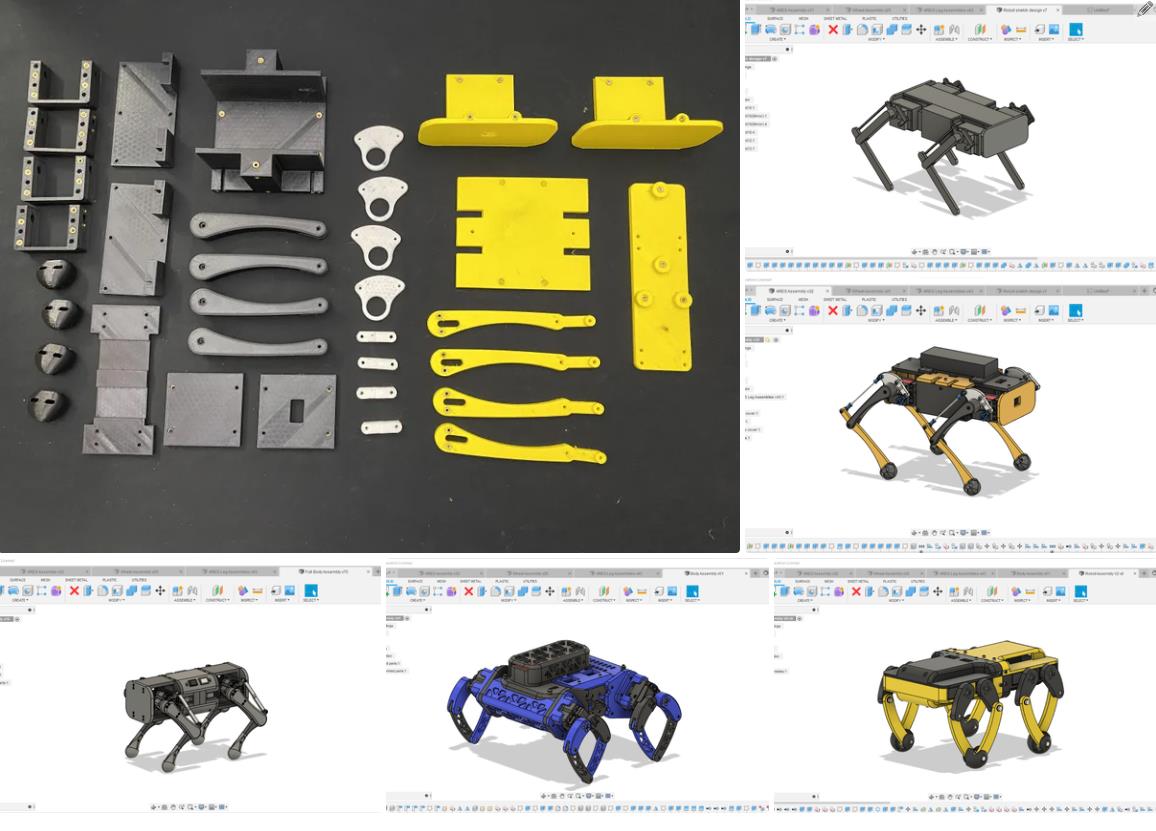
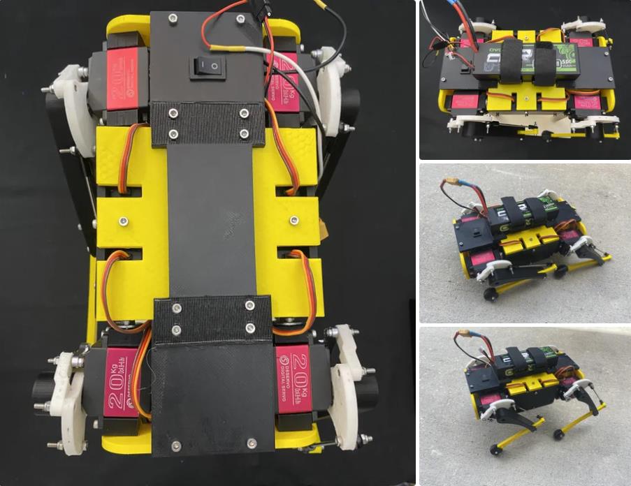
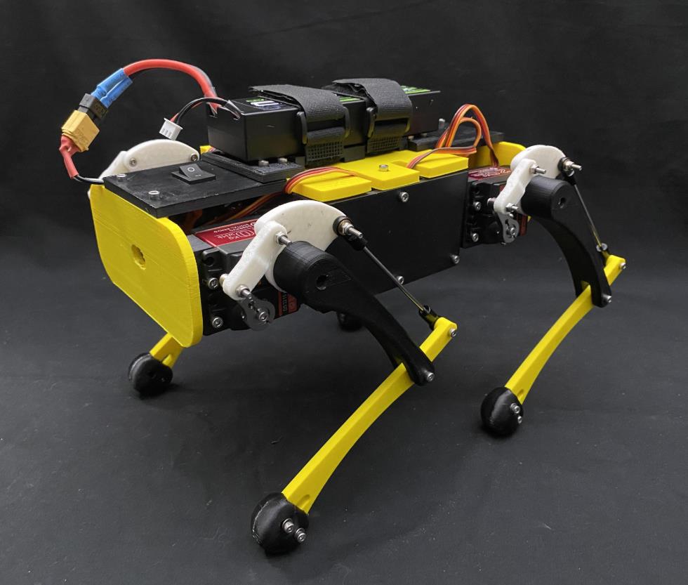
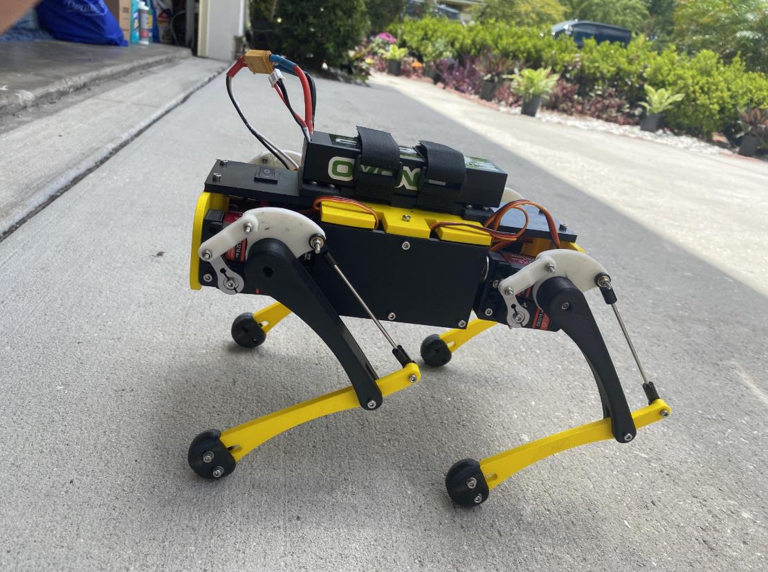
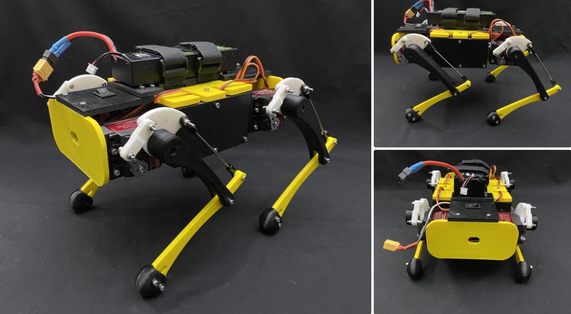
2020 年,我沉浸在四足机器人的奇妙世界中。观看 YouTube 上的机器人视频,例如 Boston Dynamics 的 SPOT 和 MIT Mini Cheetah,激发了我制作自己的机器人的灵感。这些制作巧妙的机器人以其动态动作和逼真的外观而闻名。在过去的一年里,我把创造自己的经济实惠的四足机器人作为我个人的目标。一种功能类似于高端四足动物的动物。在这里,我介绍了 ARES,这是一款完全 3D 打印的 12 DOF 机器狗,能够进行全向旅行以及许多其他机动。在这个 instructable 中,我将向您展示如何制作您自己的 ARES!
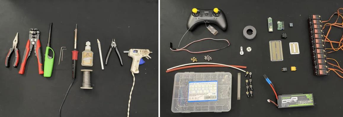
以下是构建所需的工具和用品列表
工具
尖嘴钳
剥线钳
打火机或热风枪(用于热缩管)
内六角扳手
烙铁和焊料
强力胶
Exacto 刀
剪线钳
热胶枪和热胶
用品
电子产品 ($384)
12 x DS3218 20kg 数字舵机(大多数标准尺寸的舵机也可以。确保它们是 180°)
小小 4.1
Radiolink T8S RC 控制器和接收器
12 针 Polulu Maestro 伺服控制器
3.3 至 5V 逻辑电平转换器
半原型板
迷你原型板
SPST 开关
18 AWG 电线
热缩管
XT60H 连接器对
2S (7.4v) 6200mah 锂电池
其他用品 ($146)
2 x 1 英寸魔术贴带
4 x 25T 伺服喇叭(24mm 孔中心)
8 x 25T 伺服盘
4 x M3 x 100mm 推杆连接器
8 x 22mm 长的 M3 拉杆
73 x m3 x 6mm 螺纹嵌件
16 x m3 锁紧螺母
M3 螺丝
8 x m3 x 4 毫米
35 x m3 x 6mm 螺丝
30 x m3 x 8mm 螺丝
12 x m3 x 16mm 螺丝
4 x m3 x 16mm 圆头螺钉
4 x m3 x 18mm 圆头螺钉
4 x m3 x 20mm 螺丝
4 x m3 x 22mm 螺丝
4 x m3 x 30mm 螺丝
使用耗材的总成本(不包括 3D 打印部件)= 530 USD
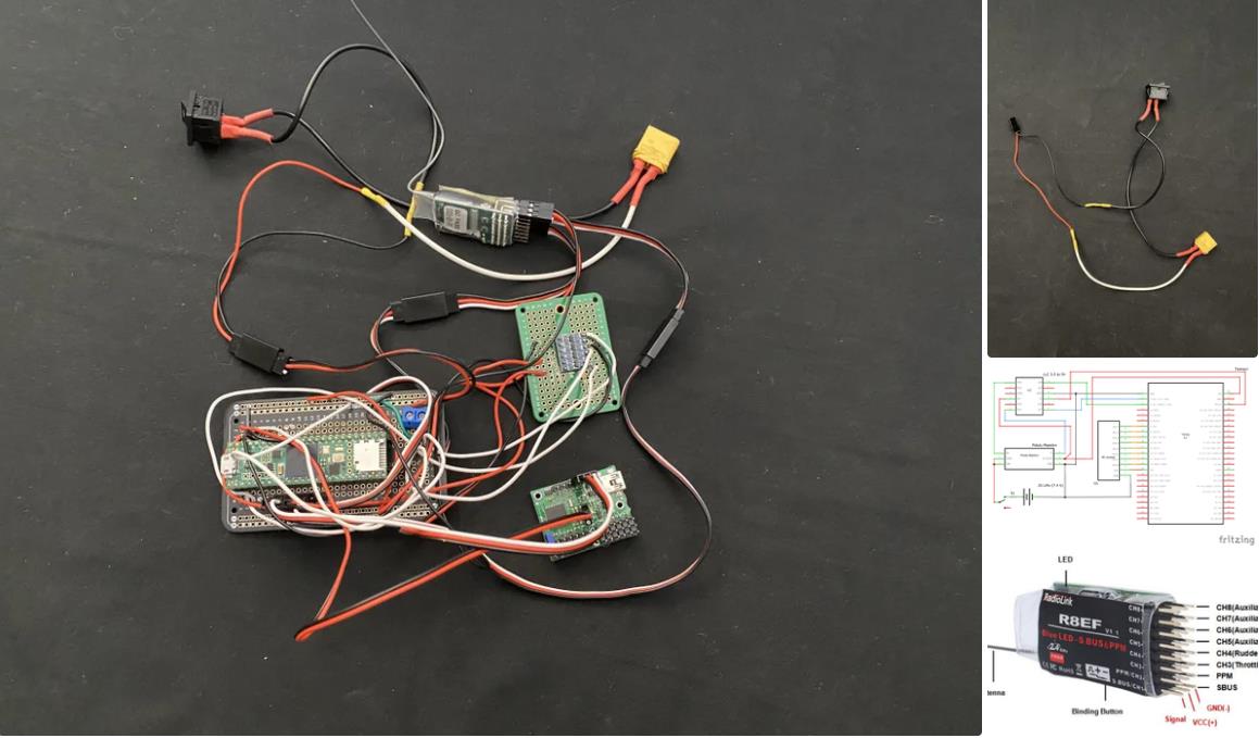
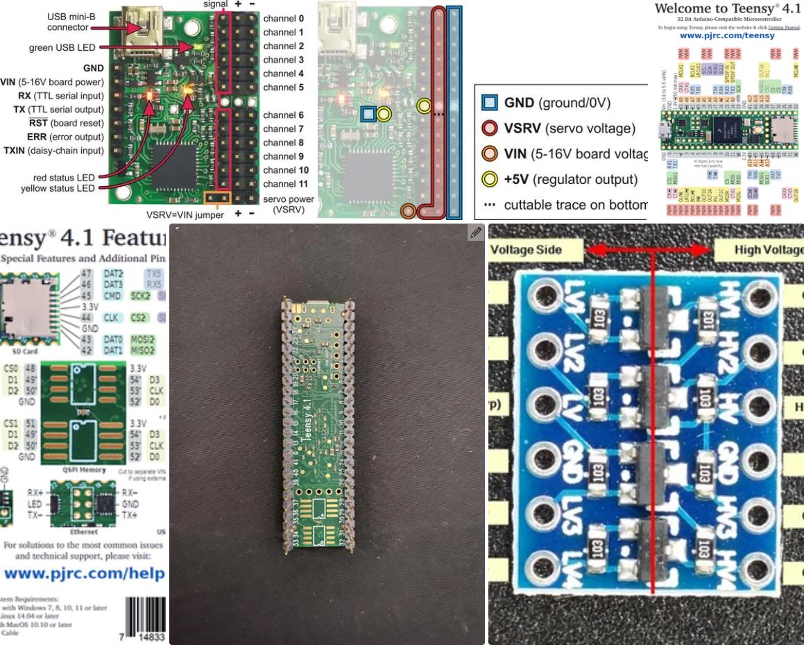
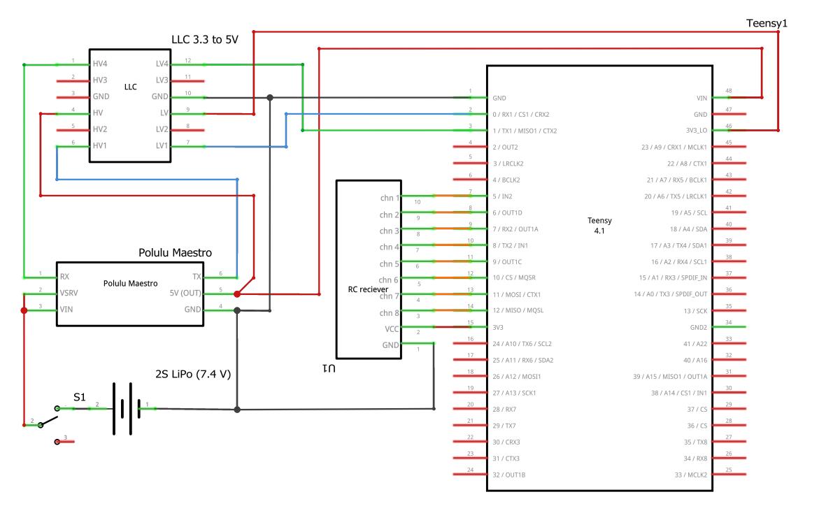
所需的电子元件:
Teensy 4.1
Radiolink T8S RC 控制器和接收器
12 针 Polulu Maestro 伺服控制器
3.3 至 5V 逻辑电平转换器
半原型板
迷你原型板
SPST 开关
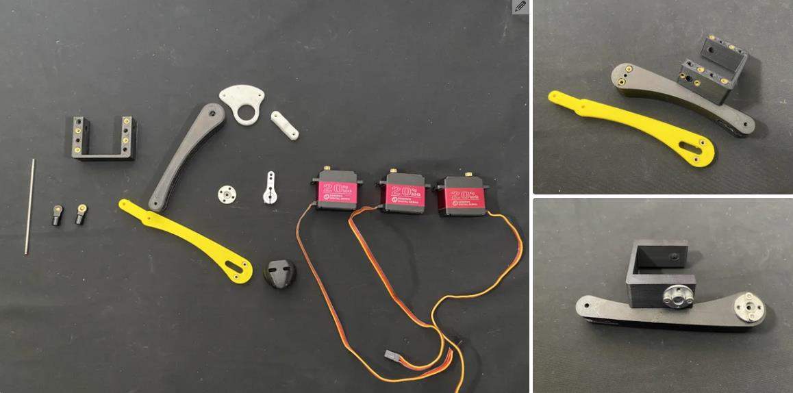
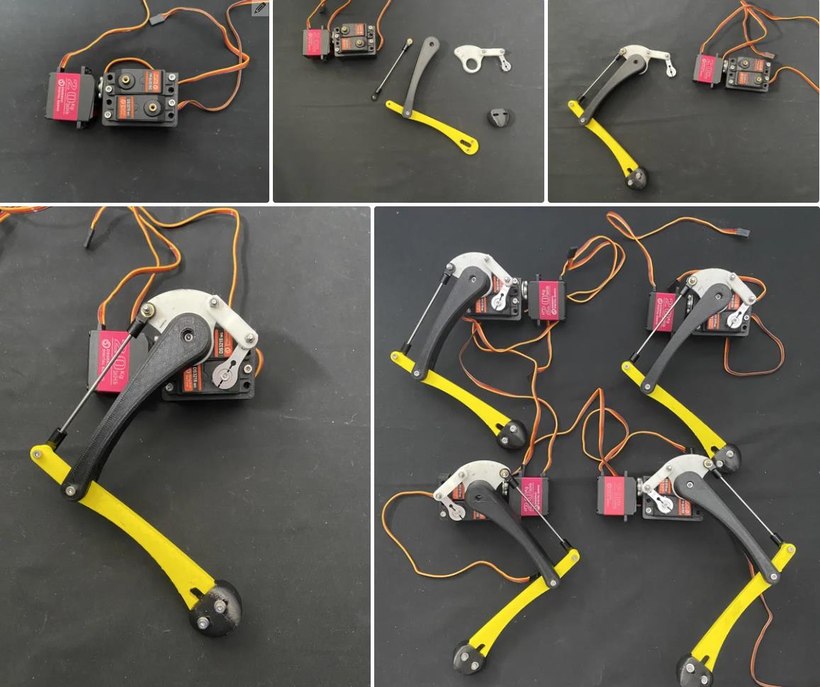
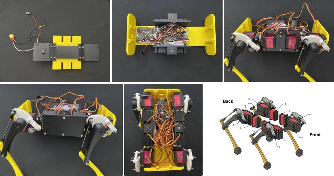
校准支腿
为机器狗创建的程序使用逆运动方程将每条腿移动到特定位置。为了使这些方程式起作用,程序必须知道每个伺服的位置。由于我们将舵机放在任意位置,因此程序无法知道舵机的位置。为了将此信息传达给程序,我们必须使用 maestro Control Center 将每个伺服移动到某个已知位置,以微秒为单位记录该位置,然后将这些位置传输到程序。上面的视频将解释如何为所有 12 个舵机获取这些位置。校准支脚后,确保重新连接连接 VSRV 和 VIN 的跳线。
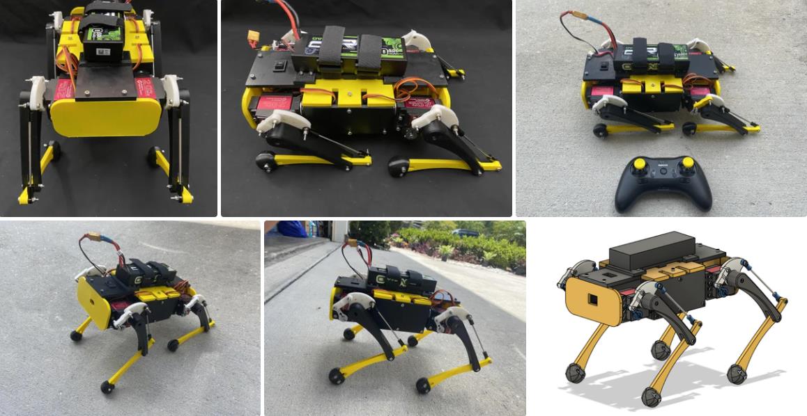
该机器人有 3 种模式。通过将通道 5(在图像 #2 上标记)移动到其向前、中性或向后位置来切换模式。
模式 1:平移(通道 5 处于中间位置)
向前或向后移动:向前或向后推动右模拟摇杆
向左或向右移动:向左或向右推动右模拟摇杆
顺时针或逆时针旋转机器人:向右或向左推动左模拟摇杆
模式 2:小跑(通道 5 向前翻转)
机器人连续在原地小跑
模式 3:倾斜(通道 5 向后翻转)
向前或向后倾斜机器人:向前或向后推动右模拟摇杆
向左或向右倾斜机器人:向左或向右推动右模拟摇杆
将机器人移回正常姿势:推动通道 6(在图像 #2 上标记)
**注意** 运行机器人时,请注意舵机的热度和 Voltage 的 LiPo 电池。伺服系统过热或电池耗尽会导致永久性损坏。
项目代码
#include <Robot_Control.h>
#include <RC_Reciever.h>

Robot Robot;
RC_Reciever reciever(5, 6, 7, 8, 9, 10, 11, 12); //define pwm pins for each channel

int Ynorm = 150; //normal Y position for each leg when the robot is in its home stance
float Yoffset;
float Yoffset2;

void setup() {
  //Start the serial monitor
  Serial.begin(115200); //baud rate
  reciever.begin(0, 180); //sets rc reciever min and max analog values

  //Servo positioning calibration
  Robot.calibrate(1500, 2000, 1930, //Front Right Leg, Servo #'s (0, 1, 2)
                  1476, 1031, 1050, //Front Left Leg, Servo #'s (3, 4, 5)
                  1423, 1897, 1870, //Back Right Leg, Servo #'s (6, 7, 8)
                  1437, 1100, 1300); //Back Left Leg, Servo #'s (9, 10, 11)

  robotHome(20); //moves robot to its home position
  delay(2000); //wait 2 seconds
}

void loop() {
  //MODE #1: TRANSLATION
  while (reciever.getChannel(5) == 0 ) { //when channel 5 is in the neutral position
    while (reciever.getChannel(2) > 140) { //if right analog stick is pushed up, move the robot forwards
      robotStep(1);
    }
    while (reciever.getChannel(2) < 40) {  //if right analog stick is pulled down, move the robot backwards
      robotStep(-1);
    }
    while (reciever.getChannel(1) > 140) { //if right analog stick is pushed right, move the robot right
      robotSlide(1);
    }
    while (reciever.getChannel(1) < 40) {  //if right analog stick is pushed left, move the robot left
      robotSlide(-1);
    }
    while (reciever.getChannel(4) > 140) { //if left analog stick is pushed right, turn the robot right
      robotTurn(1);
    }
    while (reciever.getChannel(4) < 40) {  //if left analog stick is pushed left, turn the robot left
      robotTurn(-1);
    }

    robotHome(0); //moves robot to its home position
  }

  //MODE #2: TROT
  while (reciever.getChannel(5) == 1) { //when channel 5 is flipped forward, make the robot trot
    robotTrot();
  }

  robotHome(0); //moves robot to its home position

  //MODE #3: INVERSE KINEMATICS
  while (reciever.getChannel(5) == -1 ) { //when channel 5 is flipped back
  float inc = 10;
  int Ylim = 60;
  int Ylim2 = 30;
  Robot.setSpeed(0, 0, 0, //Front Right Leg, Servo #'s (0, 1, 2)
                 0, 0, 0, //Front Left Leg, Servo #'s (3, 4, 5)
                 0, 0, 0, //Back Right Leg, Servo #'s (6, 7, 8)
                 0, 0, 0); //Back Left Leg, Servo #'s (9, 10, 11)

  if (reciever.getChannel(2) > 140) { //if right analog stick is pushed up, tilt the robot forwards
    Yoffset = Yoffset + inc;
    Yoffset = min(Yoffset, Ylim);
  }
  if (reciever.getChannel(2) < 40) {  //if right analog stick is pulled down, tilt the robot backwards
    Yoffset = Yoffset - inc;
    Yoffset = max(Yoffset, -Ylim);
  }

   if (reciever.getChannel(1) > 140) { //if right analog stick is pushed right, tilt the robot right
    Yoffset2 = Yoffset2 + inc;
    Yoffset2 = min(Yoffset2, Ylim2);
  }
  if (reciever.getChannel(1) < 40) {  //if right analog stick is pushed left, tilt the robot left
    Yoffset2 = Yoffset2 - inc;
    Yoffset2 = max(Yoffset2, -Ylim2);
  }

  if (reciever.getChannel(6) == 1) {
    robotHome(0); //moves robot to its home position
  }

  robotTilt();
}

}
【Arduino 动手做】一款完全 3D 打印的 12 DOF 机器狗
项目链接:https://www.instructables.com/3D-Printed-Robot-Dog/
项目作者:佛罗里达州杰克逊维尔 阿德穆萨
项目视频:
https://www.youtube.com/watch?v=Q3_HFzhqLwk
https://www.youtube.com/watch?v=lUotD3EdjZ4
https://www.youtube.com/watch?v=NIjodHA78UE
项目代码:
https://github.com/aaedmusa/3D-Printed-Robot-Dog/blob/main/ARES_Program.zip
https://github.com/aaedmusa/3D-Printed-Robot-Dog
3D打印文件:
https://content.instructables.com/F8F/YQ6C/L41BHFAY/F8FYQ6CL41BHFAY.f3z
https://content.instructables.com/FHP/B4XP/L41BHFB0/FHPB4XPL41BHFB0.step


 他的勋章
他的勋章

驴友花雕2025.07.25
老师好,有问题请使用中文留言,谢谢
它符合符合法定2仍无法作为2025.07.24
??????????????????????????????????????????????????????????????????????????????????????????????????????
驴友花雕2025.07.25
老师好,有问题请使用中文留言,谢谢