 返回首页
返回首页
 回到顶部
回到顶部
嗨,朋友们,我们将在这个项目中了解如何制作一台简单而出色的迷你 CNC 绘图机。几天前我在 Thingiverse 上看到了这个项目,觉得它非常有趣,所以我决定准备一个包含所有步骤的 Instructables。
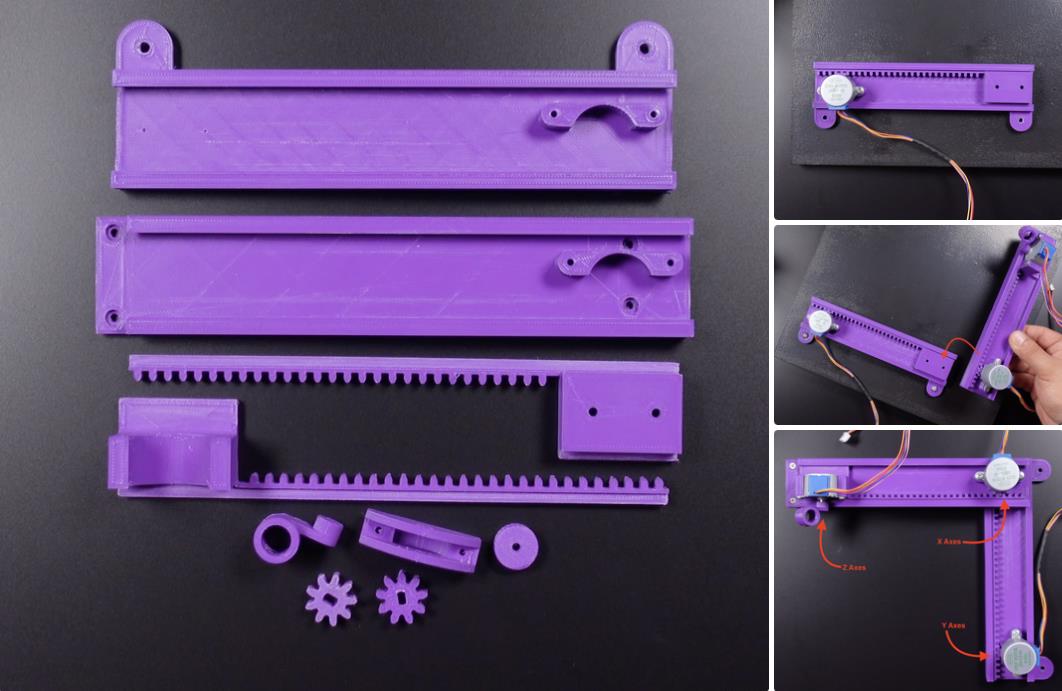
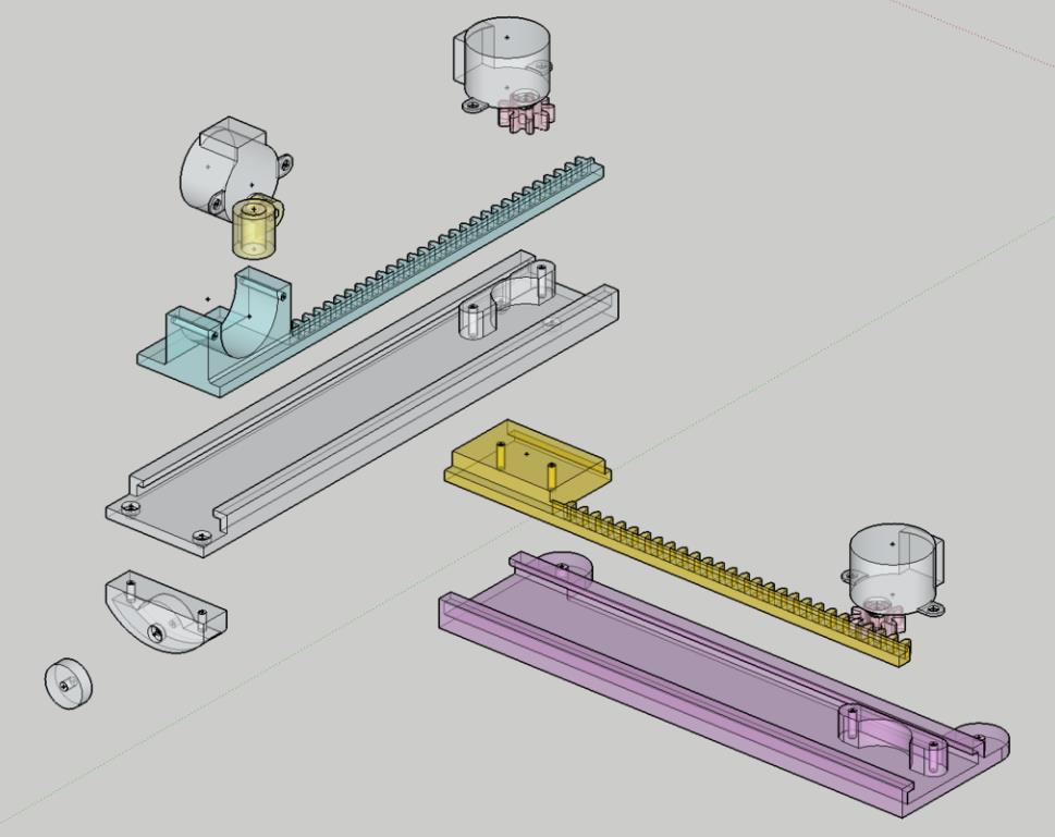
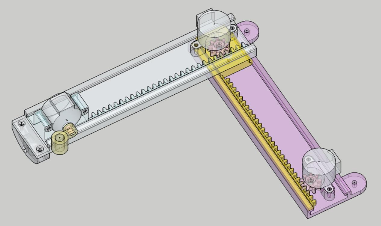
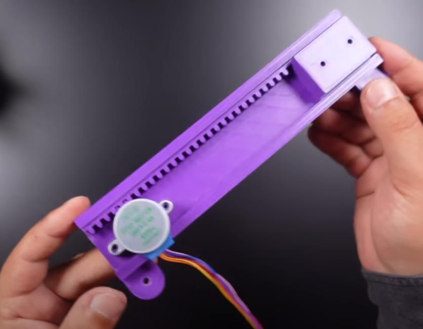
该项目基于 Arduino,包括 GRBL 代码。它包含 3 个业余步进电机和 3D 部件,可在 3 轴上提供运动。我通过组装构成项目主体结构的 3D 部件和步进电机来开始项目的第一步。3D 模型以中等质量打印,无需支撑,并且所需的螺钉类型各不相同,您可以在车间中使用兼容的尺寸。
我更新了 2 个 3D 部件,使它们更加兼容。您可以从此链接访问所有原始零件 - https://www.thingiverse.com/thing:4607077
28BYJ-48 ULN2003 5V 步进电机 - https://amzn.to/3KuDNa2
3D 打印机 - https://amzn.to/3yUe2gB
PLA 细丝 1.75mm 紫色 - https://amzn.to/4e8tR3r
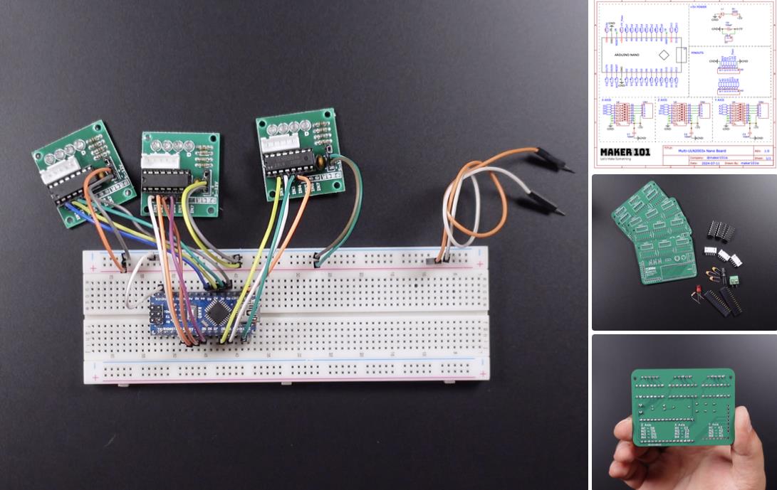
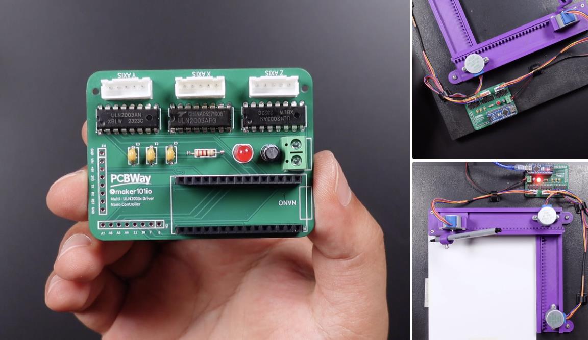
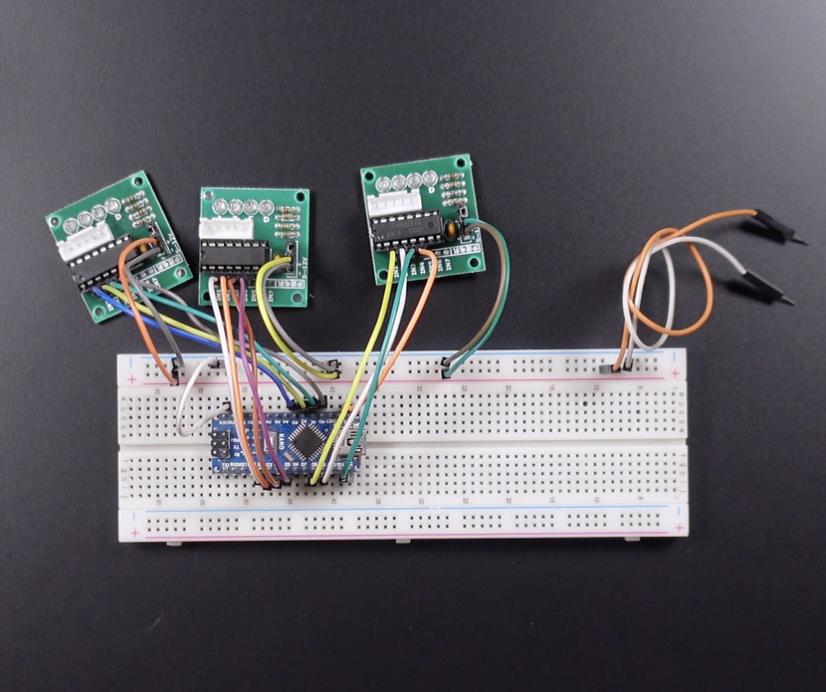
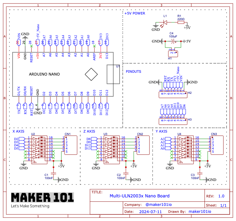
该项目的电路部分需要一个 Arduino Nano 和三个步进电机驱动器。您可以按照共享电路图在面包板上构建项目。但如您所知,我更喜欢设计和使用印刷电路板以获得更专业的原型。我在 PCBWay 项目共享页面上将我的印刷电路板设计作为开源共享。您还可以选择 PCBWay 以获得低价和高质量的印刷电路板。让我们继续组装和焊接印刷电路板中使用的组件。
电解电容器套件 (10uF 16V) - https://amzn.to/4e7wiDl
多层陶瓷电容器套件 (100nF) - https://amzn.to/456I0dB
JST-XH 连接器套件 (XH-5A) - https://amzn.to/3KuXAGw
2.54mm 公头和母头排针套件 - https://amzn.to/3yMxGva
5mm LED 发光二极管 - https://amzn.to/3VbMta2
碳膜电阻器 (220 ohm) - https://amzn.to/3Voxhb0
螺丝接线端子连接器 (5mm 2 Pin) - https://amzn.to/3X7uwMr
28BYJ-48 ULN2003 5V 步进电机 - https://amzn.to/3KuDNa2
烙铁套件 - https://amzn.to/4aPQRl3
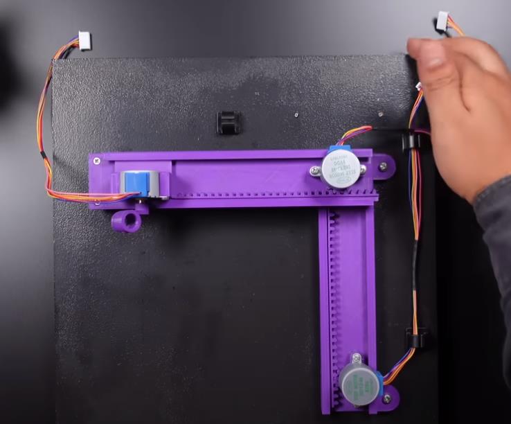
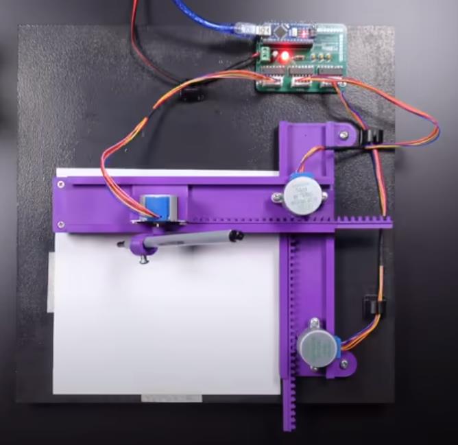
焊接后,让我们将电路板组装到项目中。每个轴输入都标记在电路板上,进行连接,然后插入 Arduino 板。电路必须由外部 5 伏电源供电,进行电源连接,然后将笔和纸连接到项目上。最后,建立 USB 连接并启动电源。
在本节中,下载并启动 G-code Sender,这是允许您配置和控制绘图仪的主要软件。首先,打开设置向导,选择 GRBL 作为固件,选择连接的端口和串行通信,然后单击连接。绘图仪将毫无问题地连接。在电机接线部分,您可以检查电机是否沿相反方向移动并进行更改。在此绘图仪中,Y 轴将反向移动。校准部分允许您通过精确移动所有轴来设置它们的初始位置。使用屏幕上的值 (100, 100, 50) 更新此绘图仪的校准截面毫米值。然后,您可以移动绘图仪轴,并在达到最佳位置时使用“重置为零”按钮完成更新。然后按 Finish 按钮,绘图仪的起始位置现在将被定义。
导入生成的 g 代码,并在屏幕上输入值 (0,991 - 0,991 - 15,113) 来更新左下角的值。这些值是与绘图仪中使用的步进电动机兼容的默认值。如果一切准备就绪,您只需按 Send 命令即可开始打印过程。
项目代码
/***********************************************************************
This sketch writes a `$I` build info string directly into Arduino EEPROM

To use:
- Just alter the "build_info_line" string to whatever you'd like. Then
  compile and upload this sketch to your Arduino.

- If your Arduino is blinking slowly, your string has already been
  written to your EEPROM and been verified by checksums! That's it!

- If you Arduino LED is blinking fast, something went wrong and the
  checksums don't match. You can optionally connect to the Arduino via
  the serial monitor, and the sketch will show what its doing.

NOTE: This sketch is provided as a tool template for OEMs who may need
to restrict users from altering their build info, so they can place
important product information here when enabling the restriction.

NOTE: When uploading Grbl to the Arduino with this sketch on it, make
sure you see the slow blink before you start the upload process. This
ensures you aren't flashing Grbl when it's in mid-write of the EEPROM.

Copyright (c) 2016 Sungeun K. Jeon for Gnea Research LLC
Released under the MIT-license. See license.txt for details.
***********************************************************************/

#include <avr/pgmspace.h>
#include <EEPROM.h>

#define SERIAL_BAUD_RATE 115200
#define LINE_LENGTH 80U    // Grbl line length
#define BYTE_LOCATION 942U // Grbl build info EEPROM address.


// ----- CHANGE THIS LINE -----

char build_info_line[LINE_LENGTH] = "Testing123.";

// -----------------------------


uint8_t status = false;
int ledPin = 13;                 // LED connected to digital pin 13

void setup() {
  Serial.begin(SERIAL_BAUD_RATE);
  delay(500);

  uint32_t address = BYTE_LOCATION;
  uint32_t size = LINE_LENGTH;
  char *write_pointer = (char*)build_info_line;
  uint8_t write_checksum = 0;
  for (; size>0; size--) {
    write_checksum = (write_checksum << 1) || (write_checksum >> 7);
    write_checksum += *write_pointer;
    EEPROM.put(address++, *(write_pointer++));
  }
  EEPROM.put(address,write_checksum);

  Serial.print(F("-> Writing line to EEPROM: '"));
  Serial.print(build_info_line);
  Serial.print(F("'\n\r-> Write checksum: "));
  Serial.println(write_checksum,DEC);

  size = LINE_LENGTH;
  address = BYTE_LOCATION;
  uint8_t data = 0;
  char read_line[LINE_LENGTH];
  char *read_pointer = (char*)read_line;
  uint8_t read_checksum = 0;
  uint8_t stored_checksum = 0;
  for(; size > 0; size--) {
    data = EEPROM.read(address++);
    read_checksum = (read_checksum << 1) || (read_checksum >> 7);
    read_checksum += data;
    *(read_pointer++) = data;
  }
  stored_checksum = EEPROM.read(address);

  Serial.print(F("<- Reading line from EEPROM: '"));
  Serial.print(read_line);
  Serial.print("'\n\r<- Read checksum: ");
  Serial.println(read_checksum,DEC);

  if ((read_checksum == write_checksum) && (read_checksum == stored_checksum)) {
    status = true;
    Serial.print(F("SUCCESS! All checksums match!\r\n"));
  } else {
    if (write_checksum != stored_checksum) {
      Serial.println(F("ERROR! Write and stored EEPROM checksums don't match!"));
    } else {
      Serial.println(F("ERROR! Read and stored checksums don't match!"));
    }
  }
  pinMode(ledPin, OUTPUT);      // sets the digital pin as output
}

void loop() {
  // Blink to let user know EEPROM write status.
  // Slow blink is 'ok'. Fast blink is an 'error'.
  digitalWrite(ledPin, HIGH);   // sets the LED on
  if (status) { delay(1500); } // Slow blink
  else { delay(100); } // Rapid blink
  digitalWrite(ledPin, LOW);    // sets the LED off
  if (status) { delay(1500); }
  else { delay(100); }
}
【Arduino 动手做】Arduino 迷你 CNC 绘图仪
项目链接:https://www.instructables.com/Arduino-Mini-CNC-Plotter/
项目作者:MertArduino
视频教程:https://www.youtube.com/watch?v=og1506q67mo
项目代码:https://github.com/TGit-Tech/GRBL-28byj-48
3D打印文件:https://www.thingiverse.com/thing:4607077
CSV文件:https://content.instructables.com/FER/WQ23/LYX004B0/FERWQ23LYX004B0.csv


 他的勋章
他的勋章


评论