 返回首页
返回首页
 回到顶部
回到顶部
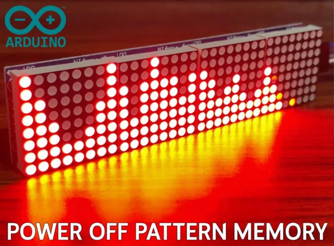
在这里,我向您介绍一个由 Arduino Nano 和 MAX 7219 4x LED 点阵面板制成的 32 频段 LED 音频频谱分析仪。包括 4 种模式,您可以使用按钮在这些模式之间循环。关机内存用于在电源重启时将所选模式保留在内存中。特别感谢“Shajeeb”,他是这个项目的原始制作者。
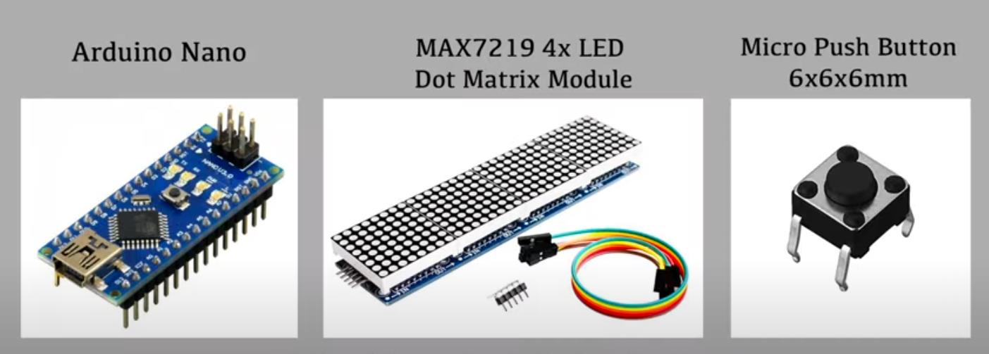
零件清单
Arduino Nano x 1
MAX 7219 4x LED 点阵 x 1
瞬时按钮 x 1
4.7K 欧姆电阻 x 3
100K 欧姆电阻器 x 1
10K 欧姆电阻器 x 1
1uF 电容器 x 2
3.5mm 立体声母插孔 x 2

项目代码
代码
// Copyright (c) 2019 Shajeeb TM
// HAZI TECH
// Updated by Hasitha Jayasundara
// Visit my YouTube Channel - http://www.youtube.com/c/HAZITECH?sub_confirmation=1

#include <arduinoFFT.h>
#include <MD_MAX72xx.h>
#include <SPI.h>
#include <EEPROM.h>

#define SAMPLES 64                                            //Must be a power of 2
#define HARDWARE_TYPE MD_MAX72XX::FC16_HW                     // Set display type  so that  MD_MAX72xx library treets it properly
#define MAX_DEVICES  4                                        // Total number display modules
#define CLK_PIN   13                                          // Clock pin to communicate with display
#define DATA_PIN  11                                          // Data pin to communicate with display
#define CS_PIN    10                                          // Control pin to communicate with display
#define  xres 32                                              // Total number of  columns in the display, must be <= SAMPLES/2
#define  yres 8                                               // Total number of  rows in the display

int audio_response = 20;                                      // put a value between 10 and 80. Smaller the number, higher the audio response

int MY_ARRAY[]={0, 128, 192, 224, 240, 248, 252, 254, 255};   // default = standard pattern
int MY_MODE_1[]={0, 128, 192, 224, 240, 248, 252, 254, 255};  // standard pattern
int MY_MODE_2[]={0, 128, 64, 32, 16, 8, 4, 2, 1};             // only peak pattern
int MY_MODE_3[]={0, 128, 192, 160, 144, 136, 132, 130, 129};  // only peak +  bottom point
int MY_MODE_4[]={0, 128, 192, 160, 208, 232, 244, 250, 253};  // one gap in the top , 3rd light onwards

double vReal[SAMPLES];
double vImag[SAMPLES];
char data_avgs[xres];

int yvalue;
int displaycolumn , displayvalue;
int peaks[xres];
const int buttonPin = 6;                                      // the number of the pushbutton pin
int state = HIGH;                                             // the current reading from the input pin
int previousState = LOW;                                      // the previous reading from the input pin
int displaymode;
unsigned long lastDebounceTime = 0;                           // the last time the output pin was toggled
unsigned long debounceDelay = 50;                             // the debounce time; increase if the output flickers

MD_MAX72XX mx = MD_MAX72XX(HARDWARE_TYPE, CS_PIN, MAX_DEVICES);   // display object
arduinoFFT FFT = arduinoFFT();                                    // FFT object

void setup() {
    EEPROM.update(1,1);                                           //(memory address, value), RUN THIS FOR THE FIRST TIME
    displaymode = EEPROM.read(1);
    ADCSRA = 0b11100101;                                          // set ADC to free running mode and set pre-scalar to 32 (0xe5)
    ADMUX = 0b00000000;                                           // use pin A0 and external voltage reference
    pinMode(buttonPin, INPUT);
    mx.begin();                                                   // initialize display
    delay(50);                                                    // wait to get reference voltage stabilized
}

void loop() {
   // ++ Sampling
   for(int i=0; i<SAMPLES; i++)
    {
      while(!(ADCSRA & 0x10));                                    // wait for ADC to complete current conversion ie ADIF bit set
      ADCSRA = 0b11110101 ;                                       // clear ADIF bit so that ADC can do next operation (0xf5)
      int value = ADC - 512 ;                                     // Read from ADC and subtract DC offset caused value
      vReal[i]= value/8;                                          // Copy to bins after compressing
      vImag[i] = 0;
    }
    // -- Sampling


    // ++ FFT
    FFT.Windowing(vReal, SAMPLES, FFT_WIN_TYP_HAMMING, FFT_FORWARD);
    FFT.Compute(vReal, vImag, SAMPLES, FFT_FORWARD);
    FFT.ComplexToMagnitude(vReal, vImag, SAMPLES);
    // -- FFT


    // ++ re-arrange FFT result to match with no. of columns on display ( xres )
    int step = (SAMPLES/2)/xres;
    int c=0;
    for(int i=0; i<(SAMPLES/2); i+=step)
    {
      data_avgs[c] = 0;
      for (int k=0 ; k< step ; k++) {
          data_avgs[c] = data_avgs[c] + vReal[i+k];
      }
      data_avgs[c] = data_avgs[c]/step;
      c++;
    }
    // -- re-arrange FFT result to match with no. of columns on display ( xres )


    // ++ send to display according measured value
    for(int i=0; i<xres; i++)
    {
      data_avgs[i] = constrain(data_avgs[i],0,audio_response);              // set max & min values for buckets
      data_avgs[i] = map(data_avgs[i], 0, audio_response, 0, yres);         // remap averaged values to yres
      yvalue=data_avgs[i];

      peaks[i] = peaks[i]-1;    // decay by one light
      if (yvalue > peaks[i])
          peaks[i] = yvalue ;
      yvalue = peaks[i];
      displayvalue=MY_ARRAY[yvalue];
      displaycolumn=31-i;
      mx.setColumn(displaycolumn, displayvalue);                // for left to right
     }
     // -- send to display according measured value

    displayModeChange ();                                       // check if button pressed to change display mode

    int reading = digitalRead(buttonPin);
    if (reading == LOW)
    {
      switch (displaymode)
      {
      case 1:    //       move from mode 1 to 2
      for (int i=0 ; i<=8 ; i++ ) {
        MY_ARRAY[i]=MY_MODE_2[i];
      }
      break;
      case 2:    //       move from mode 2 to 3
      for (int i=0 ; i<=8 ; i++ ) {
        MY_ARRAY[i]=MY_MODE_3[i];
      }
      break;
      case 3:    //     move from mode 3 to 4
      for (int i=0 ; i<=8 ; i++ ) {
        MY_ARRAY[i]=MY_MODE_4[i];
      }
      break;
      case 4:    //      move from mode 4 to 1
      for (int i=0 ; i<=8 ; i++ ) {
        MY_ARRAY[i]=MY_MODE_1[i];
      }
      break;
      }
    }
}

void displayModeChange() {
  int reading = digitalRead(buttonPin);
  if (reading == HIGH && previousState == LOW && millis() - lastDebounceTime > debounceDelay) // works only when pressed
  {
   switch (displaymode)
   {
    case 1:    //       move from mode 1 to 2
      displaymode = 2;
      EEPROM.update(1,2);
      for (int i=0 ; i<=8 ; i++ ) {
        MY_ARRAY[i]=MY_MODE_2[i];
      }
      break;
    case 2:    //       move from mode 2 to 3
      displaymode = 3;
      EEPROM.update(1,3);
      for (int i=0 ; i<=8 ; i++ ) {
        MY_ARRAY[i]=MY_MODE_3[i];
      }
      break;
    case 3:    //     move from mode 3 to 4
      displaymode = 4;
      EEPROM.update(1,4);
      for (int i=0 ; i<=8 ; i++ ) {
        MY_ARRAY[i]=MY_MODE_4[i];
      }
      break;
    case 4:    //      move from mode 4 to 1
      displaymode = 1;
      EEPROM.update(1,1);
      for (int i=0 ; i<=8 ; i++ ) {
        MY_ARRAY[i]=MY_MODE_1[i];
      }
      break;
  }
    lastDebounceTime = millis();
  }
  previousState = reading;
}
【Arduino 动手做】32 频段 LED 音频频谱分析仪 |Arduino Nano + MAX 7219
项目链接:https://github.com/HAZI-TECH/32-Band-LED-Audio-Spectrum-Analyzer?tab=readme-ov-file
项目作者:HAZI TECH
项目视频 :https://www.youtube.com/watch?v=QE2wv7v7q1U
项目代码:https://github.com/HAZI-TECH/32-Band-LED-Audio-Spectrum-Analyzer/tree/main/32_Band_LED_Spectrum_Analyzer


 他的勋章
他的勋章

评论