 返回首页
返回首页
 回到顶部
回到顶部
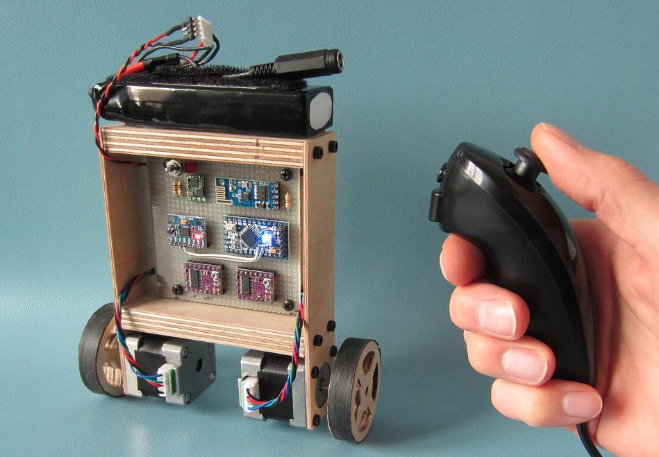
您的 Arduino 平衡机器人 (YABR) 是一款自平衡机器人,您可以将其构建为学校项目或与孩子一起构建的有趣项目。它可能看起来很简单,但您可以从构建这个自平衡机器人中学到很多东西。
与大多数自平衡机器人相比,这款机器人使用步进电机而不是常规直流电机。主要原因是步进电机精密,在电池电压下降时没有性能损失。一个脉冲始终是精确的运动量。普通直流电机可能存在机械摩擦和电阻差异。这可能会导致性能差异。因此,机器人不会沿直线移动。
如果您使用下面的硬件列表,构建此机器人的总成本约为 80 美元。这包括电池、双节棍、充电器、步进电机等。
您可以免费下载的 Arduino 程序是 100% 自编写的,不基于任何其他软件。该代码注释良好,解释清晰。这样就可以根据自己的目的进一步开发代码。
如果您在构建或设置过程中遇到任何问题,请先查看 Q&A 页面。大多数问题已经得到了详细的回答。
第 1 步 - 软件
首先下载完整的 YMFC-AL 软件包:
YABR.zip(版本 1.1)
第 2 步 - 硬件
要构建此机器人,您需要硬件。我制作以下列表只是为了方便起见。您可以从不同来源自由获取自己的硬件。但这是我使用/订购的硬件:
1 个 Arduino pro 迷你克隆
1 x FTDI USB 转 TTL 编程器,用于 Arduino pro mini
1 个 Arduino Uno 克隆
1 个 MPU-6050 陀螺仪和加速度计
2 个 2.4G 无线串行收发器模块
2 x 35mm 步进电机
2 x Geeetech StepStick DRV8825
1 x Wii 有线双节棍控制器
1 x Mini DC 7~28V 转 DC 5V 降压转换器
1 x 11.1V 2200mAh 30C 锂聚合物电池
1 个 B3AC 2S/3S 锂电池平衡充电器
如果 35mm 步进电机缺货。您也可以使用这些步进电机。请注意,这些是 42 毫米而不是 35 毫米。所以你必须修改框架。
2 x 42mm 步进电机
以下大部分零件都可以在您当地的电子商店找到。但如果你附近没有电子产品商店,我会在这里放链接:
1 x 1/4W 陶瓷金属膜电阻器套件 (600 PCS)
1 x 玻璃纤维原型 PCB
1 x 3 针拨动开关(5 件装)
最后,您需要一个旧内胎和两张胶合板。我使用了 2.5 毫米和 12.5 毫米的板材。
第 3 步 - 工具
当然,您需要一些简单的工具,例如烙铁、螺丝刀、品格锯、紧凑型钻头等。
第 4 步 - 构建
观看 YABR 硬件构建视频,并根据完整软件包中包含的视频和原理图构建机器人。
构建 YABR 平衡机器人。
我自己的 YABR 平衡机器人的详细图片可以在本项目页面的媒体部分找到。
4.1 二极管和电阻器
点击查看完整图片
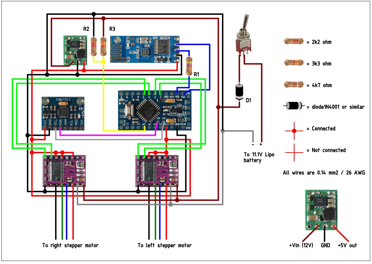
原理图上的电阻器 R1 是将程序上传到 Arduino 所必需的。收发器的 TXD 输出被强制为高电平或低电平。因此,FTDI 程序员无法再更改此输出,您将收到上传错误。通过添加此电阻器,FTDI 程序员可以更改 Arduino 的 RX 引脚上的电压,而不管收发器输出和程序的状态如何,都没有任何问题。
其他两个电阻(R2 和 R3)形成一个分压器。这意味着电池的 12.6 伏减去二极管上的 0.6 伏电压降除以 2.5。当电池充满电时,模拟输入上会产生 4.8 伏特的电压。在主程序中,此模拟输入将用于保护电池。这是因为当每节电池的电压降至 3 伏以下时,锂电池可能会损坏。
二极管 D1 保护所有电子元件免受反极性的影响。因此,当您不小心反转电池的连接时,组件不会冒烟。
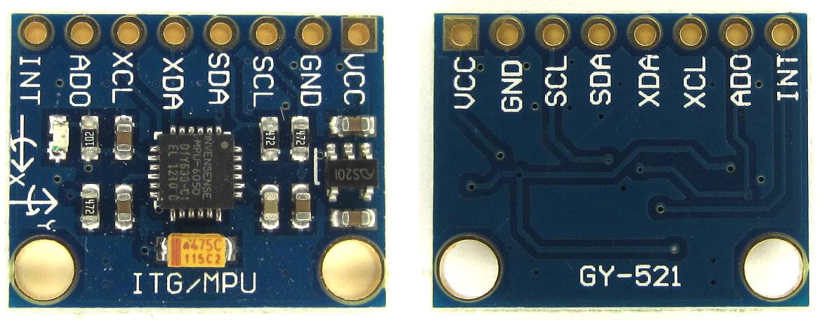
4.2 MPU-6050 陀螺仪/加速度计
点击查看完整图片
YABR 软件唯一支持的陀螺仪/加速度计是 MPU-6050。这是因为自调平功能需要一个加速度计和一个陀螺仪,正如我在这两个视频中所解释的那样:
MPU-6050 用于自动调平四轴飞行器的 6dof IMU 教程 - 第 1 部分
MPU-6050 用于自动调平四轴飞行器的 6dof IMU 教程 - 第 2 部分
陀螺仪的方向很重要。确保以与此图所示完全相同的方向安装陀螺仪。否则 YABR 软件无法计算出正确的角度,机器人将无法工作。
4.3 硬件测试
请注意,您正在焊接 PCB 背面的电线。原理图从前面面向元件绘制。所以一切都是镜像的,在将任何电源连接到 PCB 之前,您需要仔细检查所有连接。
一切就绪后,是时候将 FTDI 编程器连接到 Arduino pro mini 了。暂时不要连接电池。如果 LED 不亮,则表示接线短路,您需要尽快断开 FTDI 编程器。通常,Arduino pro mini 已经使用闪烁草图进行了编程,因此 Arduino 上的 LED 应该开始闪烁。
要检查陀螺仪是否正确连接并检查机器人的平衡点,您需要上传“hardware-check”程序,该程序可以在之前下载的软件包中找到。
测试机器人的平衡角度并将其固定在支架上的该位置,如我在视频中所示。上传 “hardware-check” 程序,打开串口监视器并将波特率设置为 9600。
上传程序后,打开串口监视器,将波特率设置为 9600。
该程序将检查是否连接了任何 I2C 设备,以及这是否是 MPU-6050。如果一切按预期工作,程序将在屏幕上输出多个原始陀螺仪值。这些只是示例,您的值可能有所不同。记下您在串行输出中看到的余额值。稍后在主程序中将需要它。
4.4 限制电机电流
待办事项列表中的下一件事是将步进控制器设置为正确的驱动电流。如果电机电流设置为高,步进控制器会发热,并且可能会损坏。
首先将电位器设置在下图所示的相同位置。现在,首次连接 lipo 电池时请务必小心。短路会导致大电流、发热、火花和灼伤。
一个好的选择是使用如下所示的小型直流保险丝。如果 PCB 背面的接线短路,该保险丝会熔断。
设置正确电流并检查接线是否正确连接的最简单、最安全的方法是使用台式电源测量电源线中的电流。电源限制为 500 毫安培。这是一项额外的安全功能。如果发生短路,电源会将电流限制为 500 毫安,接线会很好。
首先连接一个电机。使用电位计,可以将电流设置在 100 到 150mA 之间。这足以获得良好的性能。对另一个步进控制器执行相同的作。
如果您无法测量电流,只需将电位计设置在此位置,然后感觉步进驱动器是否不发热。但测量电流总是最好的。
3.5 遥控器
如果你打开 Nunchuck,你可以注意到连接到各种引脚的电线颜色,正如你在原理图上看到的那样。Nunchuck 在 3.3V 下工作,您可以使用 Arduino Uno 的 3.3V 输出为 Nunchuck 供电。
5V 输出可用于收发器。同样,按照原理图上显示的方式连接电线以使其工作。
要检查 Nunchuck 是否正确连接,您需要上传“hardware-check”程序,您可以在之前下载的软件包中找到该程序。上传程序后,打开串口监视器,将波特率设置为 9600。
该程序将检查是否连接了任何 I2C 设备,以及这是否是双节棍。如果一切按预期工作,程序将在屏幕上输出多个原始摇杆值。
第 5 步 - 上传软件
最后,您可以将 YABR-remote 程序上传到 Arduino Uno,将 YABR-robot 程序上传到 Arduino pro mini。
YABR-remote 程序不需要任何修改。在机器人程序中,您需要将加速度计校准值更改为硬件测试程序在机器人处于平衡位置时显示的值。
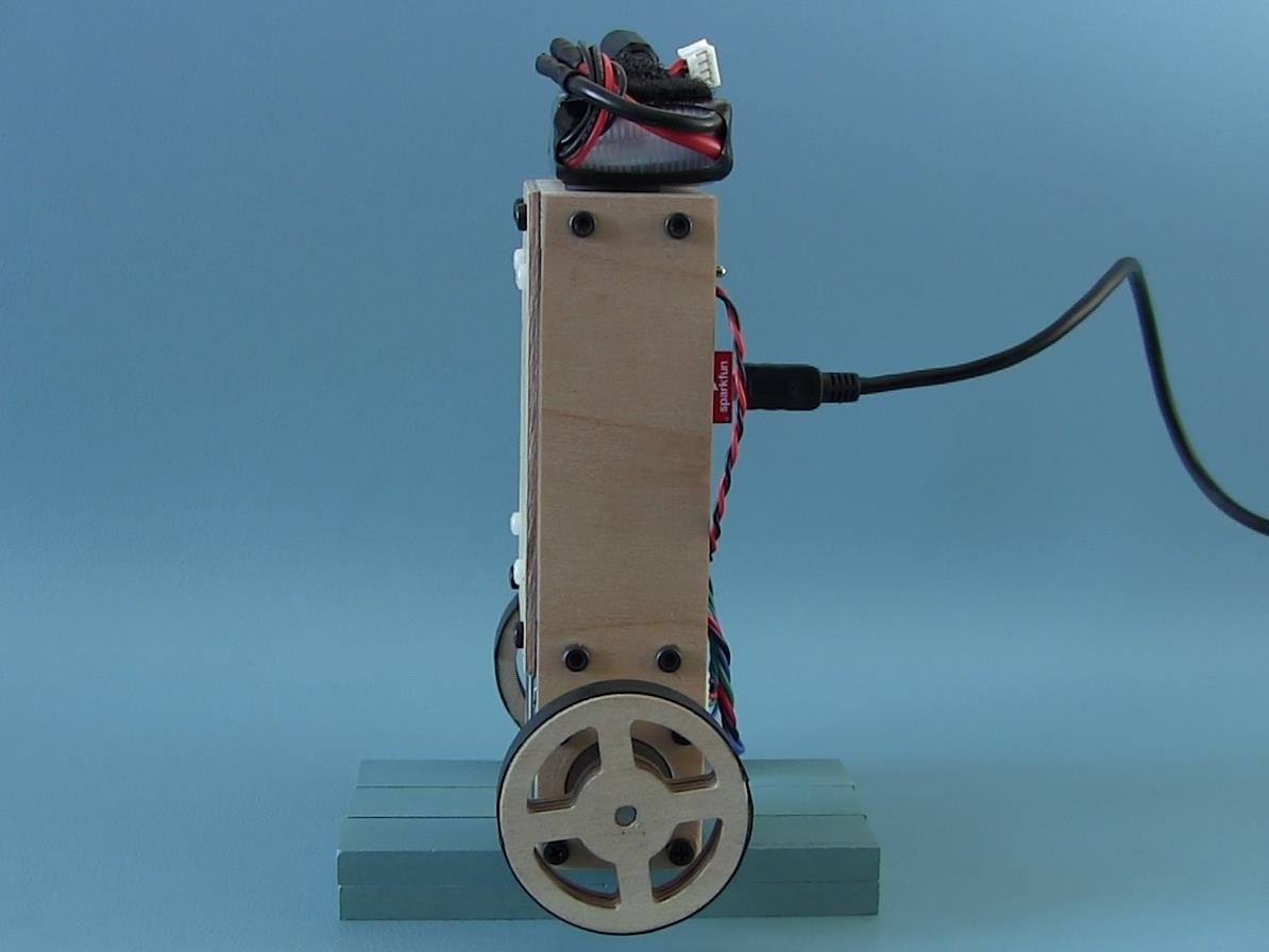
要启动机器人,您需要打开遥控器的电源。将机器人放在它的背上并打开电源。LED 将闪烁,表示陀螺仪正在校准。当闪烁停止时,您可以慢慢抬起机器人,它将自动开始自行平衡。
基本上就是这样。您现在可以使用 Nunchuck 控制机器人。

项目代码
///////////////////////////////////////////////////////////////////////////////////////
//Terms of use
///////////////////////////////////////////////////////////////////////////////////////
//THE SOFTWARE IS PROVIDED "AS IS", WITHOUT WARRANTY OF ANY KIND, EXPRESS OR
//IMPLIED, INCLUDING BUT NOT LIMITED TO THE WARRANTIES OF MERCHANTABILITY,
//FITNESS FOR A PARTICULAR PURPOSE AND NONINFRINGEMENT. IN NO EVENT SHALL THE
//AUTHORS OR COPYRIGHT HOLDERS BE LIABLE FOR ANY CLAIM, DAMAGES OR OTHER
//LIABILITY, WHETHER IN AN ACTION OF CONTRACT, TORT OR OTHERWISE, ARISING FROM,
//OUT OF OR IN CONNECTION WITH THE SOFTWARE OR THE USE OR OTHER DEALINGS IN
//THE SOFTWARE.
///////////////////////////////////////////////////////////////////////////////////////
#include <Wire.h> //Include the Wire.h library so we can communicate with the gyro
int gyro_address = 0x68; //MPU-6050 I2C address (0x68 or 0x69)
int acc_calibration_value = 1000; //Enter the accelerometer calibration value
//Various settings
float pid_p_gain = 15; //Gain setting for the P-controller (15)
float pid_i_gain = 1.5; //Gain setting for the I-controller (1.5)
float pid_d_gain = 30; //Gain setting for the D-controller (30)
float turning_speed = 30; //Turning speed (20)
float max_target_speed = 150; //Max target speed (100)
///////////////////////////////////////////////////////////////////////////////////////////////////////////////////////////////////////
//Declaring global variables
///////////////////////////////////////////////////////////////////////////////////////////////////////////////////////////////////////
byte start, received_byte, low_bat;
int left_motor, throttle_left_motor, throttle_counter_left_motor, throttle_left_motor_memory;
int right_motor, throttle_right_motor, throttle_counter_right_motor, throttle_right_motor_memory;
int battery_voltage;
int receive_counter;
int gyro_pitch_data_raw, gyro_yaw_data_raw, accelerometer_data_raw;
long gyro_yaw_calibration_value, gyro_pitch_calibration_value;
unsigned long loop_timer;
float angle_gyro, angle_acc, angle, self_balance_pid_setpoint;
float pid_error_temp, pid_i_mem, pid_setpoint, gyro_input, pid_output, pid_last_d_error;
float pid_output_left, pid_output_right;
///////////////////////////////////////////////////////////////////////////////////////////////////////////////////////////////////////
//Setup basic functions
///////////////////////////////////////////////////////////////////////////////////////////////////////////////////////////////////////
void setup(){
Serial.begin(9600); //Start the serial port at 9600 kbps
Wire.begin(); //Start the I2C bus as master
TWBR = 12; //Set the I2C clock speed to 400kHz
//To create a variable pulse for controlling the stepper motors a timer is created that will execute a piece of code (subroutine) every 20us
//This subroutine is called TIMER2_COMPA_vect
TCCR2A = 0; //Make sure that the TCCR2A register is set to zero
TCCR2B = 0; //Make sure that the TCCR2A register is set to zero
TIMSK2 |= (1 << OCIE2A); //Set the interupt enable bit OCIE2A in the TIMSK2 register
TCCR2B |= (1 << CS21); //Set the CS21 bit in the TCCRB register to set the prescaler to 8
OCR2A = 39; //The compare register is set to 39 => 20us / (1s / (16.000.000MHz / 8)) - 1
TCCR2A |= (1 << WGM21); //Set counter 2 to CTC (clear timer on compare) mode
//By default the MPU-6050 sleeps. So we have to wake it up.
Wire.beginTransmission(gyro_address); //Start communication with the address found during search.
Wire.write(0x6B); //We want to write to the PWR_MGMT_1 register (6B hex)
Wire.write(0x00); //Set the register bits as 00000000 to activate the gyro
Wire.endTransmission(); //End the transmission with the gyro.
//Set the full scale of the gyro to +/- 250 degrees per second
Wire.beginTransmission(gyro_address); //Start communication with the address found during search.
Wire.write(0x1B); //We want to write to the GYRO_CONFIG register (1B hex)
Wire.write(0x00); //Set the register bits as 00000000 (250dps full scale)
Wire.endTransmission(); //End the transmission with the gyro
//Set the full scale of the accelerometer to +/- 4g.
Wire.beginTransmission(gyro_address); //Start communication with the address found during search.
Wire.write(0x1C); //We want to write to the ACCEL_CONFIG register (1A hex)
Wire.write(0x08); //Set the register bits as 00001000 (+/- 4g full scale range)
Wire.endTransmission(); //End the transmission with the gyro
//Set some filtering to improve the raw data.
Wire.beginTransmission(gyro_address); //Start communication with the address found during search
Wire.write(0x1A); //We want to write to the CONFIG register (1A hex)
Wire.write(0x03); //Set the register bits as 00000011 (Set Digital Low Pass Filter to ~43Hz)
Wire.endTransmission(); //End the transmission with the gyro
pinMode(2, OUTPUT); //Configure digital poort 2 as output
pinMode(3, OUTPUT); //Configure digital poort 3 as output
pinMode(4, OUTPUT); //Configure digital poort 4 as output
pinMode(5, OUTPUT); //Configure digital poort 5 as output
pinMode(13, OUTPUT); //Configure digital poort 6 as output
for(receive_counter = 0; receive_counter < 500; receive_counter++){ //Create 500 loops
if(receive_counter % 15 == 0)digitalWrite(13, !digitalRead(13)); //Change the state of the LED every 15 loops to make the LED blink fast
Wire.beginTransmission(gyro_address); //Start communication with the gyro
Wire.write(0x43); //Start reading the Who_am_I register 75h
Wire.endTransmission(); //End the transmission
Wire.requestFrom(gyro_address, 4); //Request 2 bytes from the gyro
gyro_yaw_calibration_value += Wire.read()<<8|Wire.read(); //Combine the two bytes to make one integer
gyro_pitch_calibration_value += Wire.read()<<8|Wire.read(); //Combine the two bytes to make one integer
delayMicroseconds(3700); //Wait for 3700 microseconds to simulate the main program loop time
}
gyro_pitch_calibration_value /= 500; //Divide the total value by 500 to get the avarage gyro offset
gyro_yaw_calibration_value /= 500; //Divide the total value by 500 to get the avarage gyro offset
loop_timer = micros() + 4000; //Set the loop_timer variable at the next end loop time
}
///////////////////////////////////////////////////////////////////////////////////////////////////////////////////////////////////////
//Main program loop
///////////////////////////////////////////////////////////////////////////////////////////////////////////////////////////////////////
void loop(){
if(Serial.available()){ //If there is serial data available
received_byte = Serial.read(); //Load the received serial data in the received_byte variable
receive_counter = 0; //Reset the receive_counter variable
}
if(receive_counter <= 25)receive_counter ++; //The received byte will be valid for 25 program loops (100 milliseconds)
else received_byte = 0x00; //After 100 milliseconds the received byte is deleted
//Load the battery voltage to the battery_voltage variable.
//85 is the voltage compensation for the diode.
//Resistor voltage divider => (3.3k + 3.3k)/2.2k = 2.5
//12.5V equals ~5V @ Analog 0.
//12.5V equals 1023 analogRead(0).
//1250 / 1023 = 1.222.
//The variable battery_voltage holds 1050 if the battery voltage is 10.5V.
battery_voltage = (analogRead(0) * 1.222) + 85;
if(battery_voltage < 1050 && battery_voltage > 800){ //If batteryvoltage is below 10.5V and higher than 8.0V
digitalWrite(13, HIGH); //Turn on the led if battery voltage is to low
low_bat = 1; //Set the low_bat variable to 1
}
///////////////////////////////////////////////////////////////////////////////////////////////////////////////////////////////////////
//Angle calculations
///////////////////////////////////////////////////////////////////////////////////////////////////////////////////////////////////////
Wire.beginTransmission(gyro_address); //Start communication with the gyro
Wire.write(0x3F); //Start reading at register 3F
Wire.endTransmission(); //End the transmission
Wire.requestFrom(gyro_address, 2); //Request 2 bytes from the gyro
accelerometer_data_raw = Wire.read()<<8|Wire.read(); //Combine the two bytes to make one integer
accelerometer_data_raw += acc_calibration_value; //Add the accelerometer calibration value
if(accelerometer_data_raw > 8200)accelerometer_data_raw = 8200; //Prevent division by zero by limiting the acc data to +/-8200;
if(accelerometer_data_raw < -8200)accelerometer_data_raw = -8200; //Prevent division by zero by limiting the acc data to +/-8200;
angle_acc = asin((float)accelerometer_data_raw/8200.0)* 57.296; //Calculate the current angle according to the accelerometer
if(start == 0 && angle_acc > -0.5&& angle_acc < 0.5){ //If the accelerometer angle is almost 0
angle_gyro = angle_acc; //Load the accelerometer angle in the angle_gyro variable
start = 1; //Set the start variable to start the PID controller
}
Wire.beginTransmission(gyro_address); //Start communication with the gyro
Wire.write(0x43); //Start reading at register 43
Wire.endTransmission(); //End the transmission
Wire.requestFrom(gyro_address, 4); //Request 4 bytes from the gyro
gyro_yaw_data_raw = Wire.read()<<8|Wire.read(); //Combine the two bytes to make one integer
gyro_pitch_data_raw = Wire.read()<<8|Wire.read(); //Combine the two bytes to make one integer
gyro_pitch_data_raw -= gyro_pitch_calibration_value; //Add the gyro calibration value
angle_gyro += gyro_pitch_data_raw * 0.000031; //Calculate the traveled during this loop angle and add this to the angle_gyro variable
///////////////////////////////////////////////////////////////////////////////////////////////////////////////////////////////////////
//MPU-6050 offset compensation
///////////////////////////////////////////////////////////////////////////////////////////////////////////////////////////////////////
//Not every gyro is mounted 100% level with the axis of the robot. This can be cause by misalignments during manufacturing of the breakout board.
//As a result the robot will not rotate at the exact same spot and start to make larger and larger circles.
//To compensate for this behavior a VERY SMALL angle compensation is needed when the robot is rotating.
//Try 0.0000003 or -0.0000003 first to see if there is any improvement.
gyro_yaw_data_raw -= gyro_yaw_calibration_value; //Add the gyro calibration value
//Uncomment the following line to make the compensation active
//angle_gyro -= gyro_yaw_data_raw * 0.0000003; //Compensate the gyro offset when the robot is rotating
angle_gyro = angle_gyro * 0.9996 + angle_acc * 0.0004; //Correct the drift of the gyro angle with the accelerometer angle
///////////////////////////////////////////////////////////////////////////////////////////////////////////////////////////////////////
//PID controller calculations
///////////////////////////////////////////////////////////////////////////////////////////////////////////////////////////////////////
//The balancing robot is angle driven. First the difference between the desired angel (setpoint) and actual angle (process value)
//is calculated. The self_balance_pid_setpoint variable is automatically changed to make sure that the robot stays balanced all the time.
//The (pid_setpoint - pid_output * 0.015) part functions as a brake function.
pid_error_temp = angle_gyro - self_balance_pid_setpoint - pid_setpoint;
if(pid_output > 10 || pid_output < -10)pid_error_temp += pid_output * 0.015 ;
pid_i_mem += pid_i_gain * pid_error_temp; //Calculate the I-controller value and add it to the pid_i_mem variable
if(pid_i_mem > 400)pid_i_mem = 400; //Limit the I-controller to the maximum controller output
else if(pid_i_mem < -400)pid_i_mem = -400;
//Calculate the PID output value
pid_output = pid_p_gain * pid_error_temp + pid_i_mem + pid_d_gain * (pid_error_temp - pid_last_d_error);
if(pid_output > 400)pid_output = 400; //Limit the PI-controller to the maximum controller output
else if(pid_output < -400)pid_output = -400;
pid_last_d_error = pid_error_temp; //Store the error for the next loop
if(pid_output < 5 && pid_output > -5)pid_output = 0; //Create a dead-band to stop the motors when the robot is balanced
if(angle_gyro > 30 || angle_gyro < -30 || start == 0 || low_bat == 1){ //If the robot tips over or the start variable is zero or the battery is empty
pid_output = 0; //Set the PID controller output to 0 so the motors stop moving
pid_i_mem = 0; //Reset the I-controller memory
start = 0; //Set the start variable to 0
self_balance_pid_setpoint = 0; //Reset the self_balance_pid_setpoint variable
}
///////////////////////////////////////////////////////////////////////////////////////////////////////////////////////////////////////
//Control calculations
///////////////////////////////////////////////////////////////////////////////////////////////////////////////////////////////////////
pid_output_left = pid_output; //Copy the controller output to the pid_output_left variable for the left motor
pid_output_right = pid_output; //Copy the controller output to the pid_output_right variable for the right motor
if(received_byte & B00000001){ //If the first bit of the receive byte is set change the left and right variable to turn the robot to the left
pid_output_left += turning_speed; //Increase the left motor speed
pid_output_right -= turning_speed; //Decrease the right motor speed
}
if(received_byte & B00000010){ //If the second bit of the receive byte is set change the left and right variable to turn the robot to the right
pid_output_left -= turning_speed; //Decrease the left motor speed
pid_output_right += turning_speed; //Increase the right motor speed
}
if(received_byte & B00000100){ //If the third bit of the receive byte is set change the left and right variable to turn the robot to the right
if(pid_setpoint > -2.5)pid_setpoint -= 0.05; //Slowly change the setpoint angle so the robot starts leaning forewards
if(pid_output > max_target_speed * -1)pid_setpoint -= 0.005; //Slowly change the setpoint angle so the robot starts leaning forewards
}
if(received_byte & B00001000){ //If the forth bit of the receive byte is set change the left and right variable to turn the robot to the right
if(pid_setpoint < 2.5)pid_setpoint += 0.05; //Slowly change the setpoint angle so the robot starts leaning backwards
if(pid_output < max_target_speed)pid_setpoint += 0.005; //Slowly change the setpoint angle so the robot starts leaning backwards
}
if(!(received_byte & B00001100)){ //Slowly reduce the setpoint to zero if no foreward or backward command is given
if(pid_setpoint > 0.5)pid_setpoint -=0.05; //If the PID setpoint is larger then 0.5 reduce the setpoint with 0.05 every loop
else if(pid_setpoint < -0.5)pid_setpoint +=0.05; //If the PID setpoint is smaller then -0.5 increase the setpoint with 0.05 every loop
else pid_setpoint = 0; //If the PID setpoint is smaller then 0.5 or larger then -0.5 set the setpoint to 0
}
//The self balancing point is adjusted when there is not forward or backwards movement from the transmitter. This way the robot will always find it's balancing point
if(pid_setpoint == 0){ //If the setpoint is zero degrees
if(pid_output < 0)self_balance_pid_setpoint += 0.0015; //Increase the self_balance_pid_setpoint if the robot is still moving forewards
if(pid_output > 0)self_balance_pid_setpoint -= 0.0015; //Decrease the self_balance_pid_setpoint if the robot is still moving backwards
}
///////////////////////////////////////////////////////////////////////////////////////////////////////////////////////////////////////
//Motor pulse calculations
///////////////////////////////////////////////////////////////////////////////////////////////////////////////////////////////////////
//To compensate for the non-linear behaviour of the stepper motors the folowing calculations are needed to get a linear speed behaviour.
if(pid_output_left > 0)pid_output_left = 405 - (1/(pid_output_left + 9)) * 5500;
else if(pid_output_left < 0)pid_output_left = -405 - (1/(pid_output_left - 9)) * 5500;
if(pid_output_right > 0)pid_output_right = 405 - (1/(pid_output_right + 9)) * 5500;
else if(pid_output_right < 0)pid_output_right = -405 - (1/(pid_output_right - 9)) * 5500;
//Calculate the needed pulse time for the left and right stepper motor controllers
if(pid_output_left > 0)left_motor = 400 - pid_output_left;
else if(pid_output_left < 0)left_motor = -400 - pid_output_left;
else left_motor = 0;
if(pid_output_right > 0)right_motor = 400 - pid_output_right;
else if(pid_output_right < 0)right_motor = -400 - pid_output_right;
else right_motor = 0;
//Copy the pulse time to the throttle variables so the interrupt subroutine can use them
throttle_left_motor = left_motor;
throttle_right_motor = right_motor;
///////////////////////////////////////////////////////////////////////////////////////////////////////////////////////////////////////
//Loop time timer
///////////////////////////////////////////////////////////////////////////////////////////////////////////////////////////////////////
//The angle calculations are tuned for a loop time of 4 milliseconds. To make sure every loop is exactly 4 milliseconds a wait loop
//is created by setting the loop_timer variable to +4000 microseconds every loop.
while(loop_timer > micros());
loop_timer += 4000;
}
///////////////////////////////////////////////////////////////////////////////////////////////////////////////////////////////////////
//Interrupt routine TIMER2_COMPA_vect
///////////////////////////////////////////////////////////////////////////////////////////////////////////////////////////////////////
ISR(TIMER2_COMPA_vect){
//Left motor pulse calculations
throttle_counter_left_motor ++; //Increase the throttle_counter_left_motor variable by 1 every time this routine is executed
if(throttle_counter_left_motor > throttle_left_motor_memory){ //If the number of loops is larger then the throttle_left_motor_memory variable
throttle_counter_left_motor = 0; //Reset the throttle_counter_left_motor variable
throttle_left_motor_memory = throttle_left_motor; //Load the next throttle_left_motor variable
if(throttle_left_motor_memory < 0){ //If the throttle_left_motor_memory is negative
PORTD &= 0b11110111; //Set output 3 low to reverse the direction of the stepper controller
throttle_left_motor_memory *= -1; //Invert the throttle_left_motor_memory variable
}
else PORTD |= 0b00001000; //Set output 3 high for a forward direction of the stepper motor
}
else if(throttle_counter_left_motor == 1)PORTD |= 0b00000100; //Set output 2 high to create a pulse for the stepper controller
else if(throttle_counter_left_motor == 2)PORTD &= 0b11111011; //Set output 2 low because the pulse only has to last for 20us
//right motor pulse calculations
throttle_counter_right_motor ++; //Increase the throttle_counter_right_motor variable by 1 every time the routine is executed
if(throttle_counter_right_motor > throttle_right_motor_memory){ //If the number of loops is larger then the throttle_right_motor_memory variable
throttle_counter_right_motor = 0; //Reset the throttle_counter_right_motor variable
throttle_right_motor_memory = throttle_right_motor; //Load the next throttle_right_motor variable
if(throttle_right_motor_memory < 0){ //If the throttle_right_motor_memory is negative
PORTD |= 0b00100000; //Set output 5 low to reverse the direction of the stepper controller
throttle_right_motor_memory *= -1; //Invert the throttle_right_motor_memory variable
}
else PORTD &= 0b11011111; //Set output 5 high for a forward direction of the stepper motor
}
else if(throttle_counter_right_motor == 1)PORTD |= 0b00010000; //Set output 4 high to create a pulse for the stepper controller
else if(throttle_counter_right_motor == 2)PORTD &= 0b11101111; //Set output 4 low because the pulse only has to last for 20us
}【Arduino 动手做】YABR:一款使用步进电机的自平衡机器人
项目链接:http://www.brokking.net/yabr_main.html
项目作者:Joop Brokking
项目视频 :https://www.youtube.com/watch?v=6WWqo-Yr8lA
项目代码:http://77.161.83.3/cgi-bin/yabr.cgi


 他的勋章
他的勋章

评论