 返回首页
返回首页
 回到顶部
回到顶部
一年前,我和儿子一起制作了一个简单的 Arduino 骰子。在此期间,我们学到了很多东西,是时候进行更新了......
本项目使用的东西
硬件组件
Arduino Nano R3
× 1
3mm 8x8 点阵MAX7219
× 1
倾斜开关模块和数字接口
× 1
滑动开关
× 1
MT3608 DC 2A 升压电源模块 2V-24V 转 5V/9V/12V/28V 升压转换器
× 1
软件应用程序和在线服务
Arduino IDE
Autodesk Fusion
手动工具和制造机
烙铁(通用)
热胶枪(通用)
项目故事
大约一年前,我和我儿子用 Arduino 和一些 LED 制作了一个电子骰子。对于初学者来说,这仍然是一个理想的项目。今年我们学到了很多东西,所以现在是更新的时候了。
骰子仍然是一个完美的入门项目。功能对每个人都很清楚,并且很容易理解不同的领域:微控制器、简单的电子设备和编码。
版本 2.0
骰子也很棒,更进一步:连接其他区域。
今天,几乎所有东西都有一个现成的组件。在寻找 Arduino 或 Raspberry Pi 的入门套件时,最好看到这一点。LED、按钮和任何类型的传感器等组件都构建在电路板上,因此只需几根电线即可连接到 GPIO 并使用。
简单但足够的 3D 打印机在 ebay 上以不到 140 欧元的价格买到。几乎所有的支架、安装或外壳都可以用它创建。
还有更多机会来开发您自己的项目。这方面的一个例子是我们的新骰子 2.0。
倾斜传感器
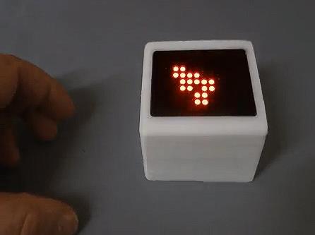
我们以完全不同的方式实现骰子。在内部,由于空间原因,Arduino Nano 正在工作。仍然有一个开关,但没有按钮。通过摇动整个立方体来完成切块。
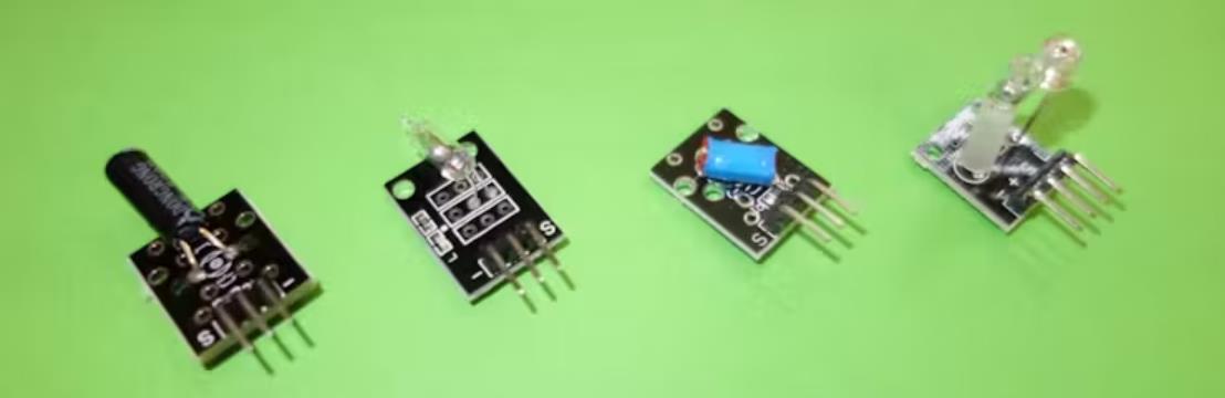
为此,使用了倾斜传感器或振动传感器。它们就像一个按钮一样工作。在玻璃管中,球移动。如果它碰到连接触点,则电路闭合。这个触点有时很短,用于信号。
如果您摇动传感器,可以很好地听到金属球的运动。
通常,安装位置对于倾斜传感器起决定性作用。它应该在某个角度位置触发信号。在我们的例子中,这是通过摇动外壳来实现的。这里的情况并不那么重要,因为当向任何方向摇晃时,都会触发信号。为了安全起见,我们在项目中使用了两个传感器,它们彼此偏移 90°。因此,我们总是能得到可靠的摇动信号。
中断
为了能够在晃动时识别,必须在草图中查询倾斜传感器的输入引脚。但是,根据这种情况何时发生以及草图还必须做什么,总是有可能一个或多个事件被忽视。
更好的解决方案是使用硬件中断。这是由函数 attachInterrupt 定义的。作为参数,指定一个子程序,该子程序将在信号上调用。
Arduino 提供两个硬件中断:引脚 D2 和 D3。
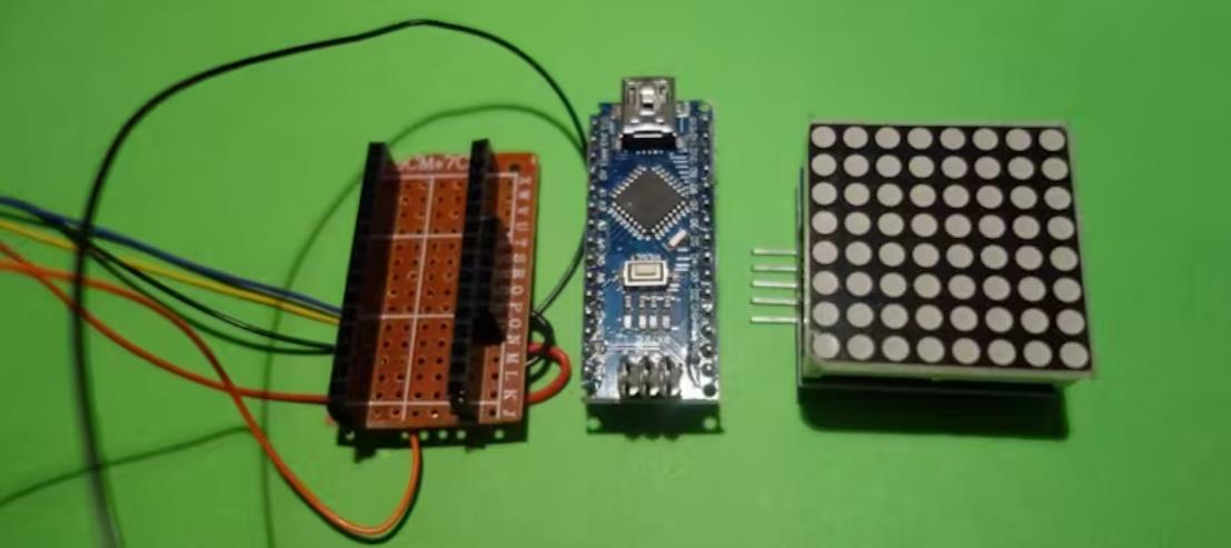
显示
当然,骰子图像的显示也可以再次通过 7 个单独的 LED 来完成。但在这里使用 finished component 也更有趣。
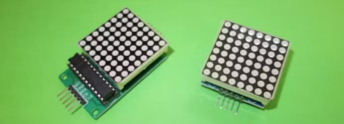
我们在这个项目中选择了很多带有 MAX7219 驱动器 IC 的 8x8 LED 矩阵。它占用的空间非常小,成本很小,而且易于编码。
根据你在哪里买到它,你必须焊接在一起并组装单个部件。这通常没问题。唯一可能犯的错误是将 LED 矩阵拧入插孔。
如上图所示。在这里,小心地将矩阵从插座中拉出并将其旋转 180° 就足够了。
一些物理学
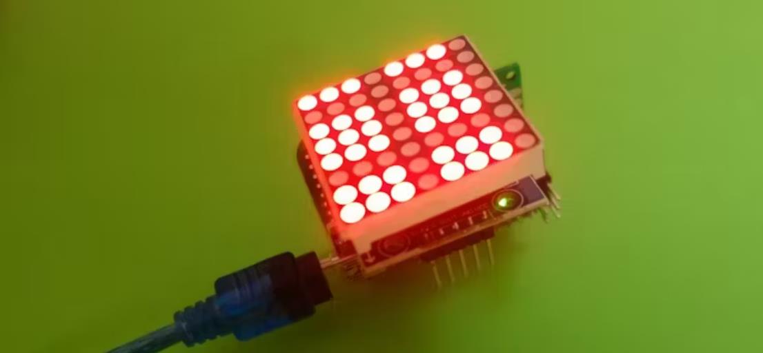
LED 矩阵不应仅显示骰子图像。它应该提供一些 show 效果。六个骰子眼睛在矩阵上移动:它们从边缘反弹并慢慢失去速度。
通过两个倾斜传感器,我们可以看到发生了多少摇晃。我们给骰子眼睛的这个信息作为他们移动的 “速度”。
我们在显示骰子结果时也使用了类似的效果。眼睛从随机位置滚动到立方体图像中的正确位置。
电源
首先,由于空间原因,我们安装了两个 3V CR2032 纽扣电池。一开始看起来也不错。Arduino 和 LED 矩阵配合工作,一切正常。然而,运行几分钟后,纽扣电池的功率就坏了。
如果你在每次掷骰子后关闭 Arduino,你可以以这种方式使用它。这并不完美,因此我们安装了两节更好的 AAA 电池。但是,这些只能一起提供 3V 电压。所以我们仍然需要一个升压转换器,将电压提高到 5V。连接仍然发生在 Arduino 的 VIN 引脚上。
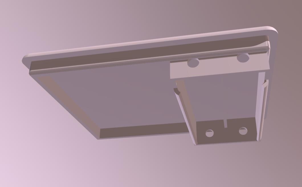
外壳设计
合适外壳的最佳选择是通过 3D 打印进行自主设计和生产。有许多用于施工的应用程序。我们在这个项目中使用了 Autodesk Fusion 360。它具有出色的功能,并且 3D 打印与 Print Studio 软件完美集成。如果您对 Autodesk Fusion 360 感兴趣,可以在博客文章参数化外壳(仅德语)中找到一些建议。
我们的外壳由 3 部分组成:
大壳
带电池座的小壳,用于 AAA 电池
Plexiglas 盖(不一定非得如此)
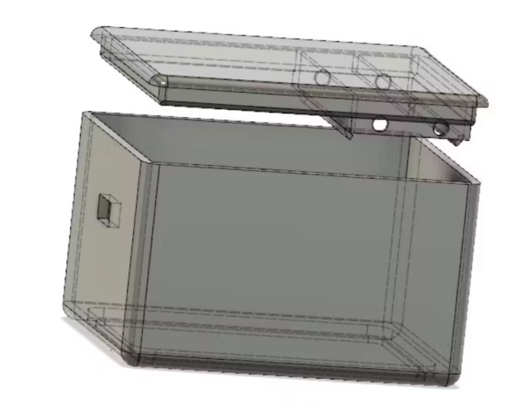
LED 矩阵前面有一个乳白色的有机玻璃盖,看起来更好。这使得无法识别关闭的 LED,并且图像更清晰。
驱动
要控制 LED 矩阵,需要 LedControl 库。如果尚未安装,可以从 arduino.cc https://playground.arduino.cc/Main/LedControl 下载。
然后我们进行其他变量定义。首先,我们确定骰子眼睛在矩阵上的显示方式。一个骰子眼由 4 个 LED 点组成。在数组中,左上角指定为 X / Y 坐标(-1 表示在显示之外)。
int DicePic[8][6][2] = { …
{ //1:
{4,4}, //1. Punkt
{-1,-1}, //2. Punkt
{-1,-1}, //3. Punkt
{-1,-1}, //4. Punkt
{-1,-1}, //5. Punkt
{-1,-1} //6. Punkt },
{ //2:
{2,2}, //1. Punkt
{6,6}, //2. Punkt
{-1,-1}, //3. Punkt
{-1,-1}, //4. Punkt
{-1,-1}, //5. Punkt
{-1,-1} //6. Punkt }, …
当然,这里一切皆有可能。让您的想象力自由驰骋。它并不总是典型的眼睛图像。
您可以在代码中直接找到其他注释。
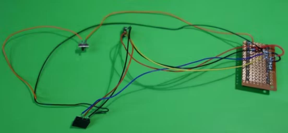
组合
我们将 Arduino 放在插座板上,作为一种扩展板。LED 矩阵的五个触点以相同的方式连接。如果 Arduino 居中,则最好使用空间。因此,最好将引脚 5、6、7 用于矩阵的 CS、CLK 和 DIN。此时只需连接焊点。与 5V 和 GND 的连接是通过一个小跳线进行的。
我们还用短线连接两个倾斜传感器。它们连接到引脚 2 和 3 以及 5V 和 GND。
现在一切都可以组装了。首先用热胶固定有机玻璃。我们对 LED 矩阵执行相同的作。一小点热胶就足够了。
接下来,安装 on/off 开关,用热胶固定并连接到适当的电线。
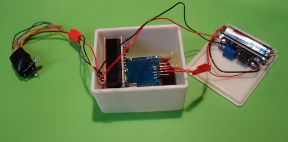
安装电源
电源有点修补。根据您拥有的选项和组件,正号和负号的触点可以相应地进行拉延筋对等值。
我们使用用过的电池仓中的弹簧和销钉。为了连接到外壳底部,我们再次使用电线和少许热胶。
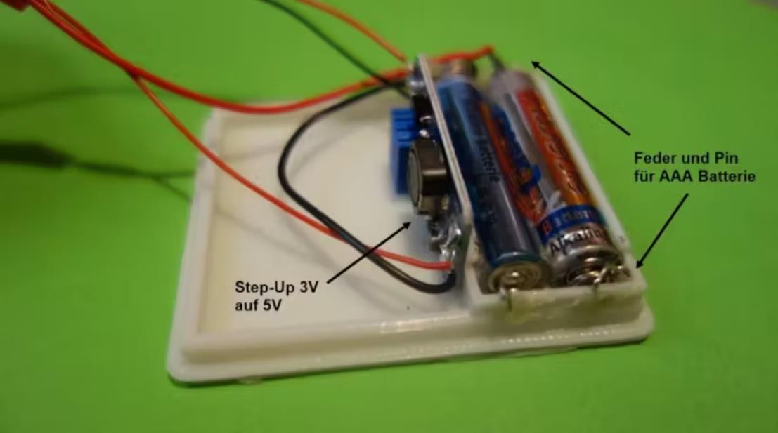
升压升压转换器最好在安装前调整到大约 5V。为此,阻力必须稍微扭转。
然后将大写和小写放在一起。由于贴合度为 0.1 mm,无需进一步固定即可插入在一起。而且它们仍然可以再次打开更换电池。
然后就完成了!
骰子乐趣 2.0 可以开始了!
所需条件
Arduino Nano(或 ESP8266)
2 x 倾斜传感器(带集成电阻器)
8x8 LED 矩阵,带 MAX7219 IC、SPC
插座板
开/关开关
印刷电路板
2 节 AAA 电池
定制零件和外壳
外壳上部
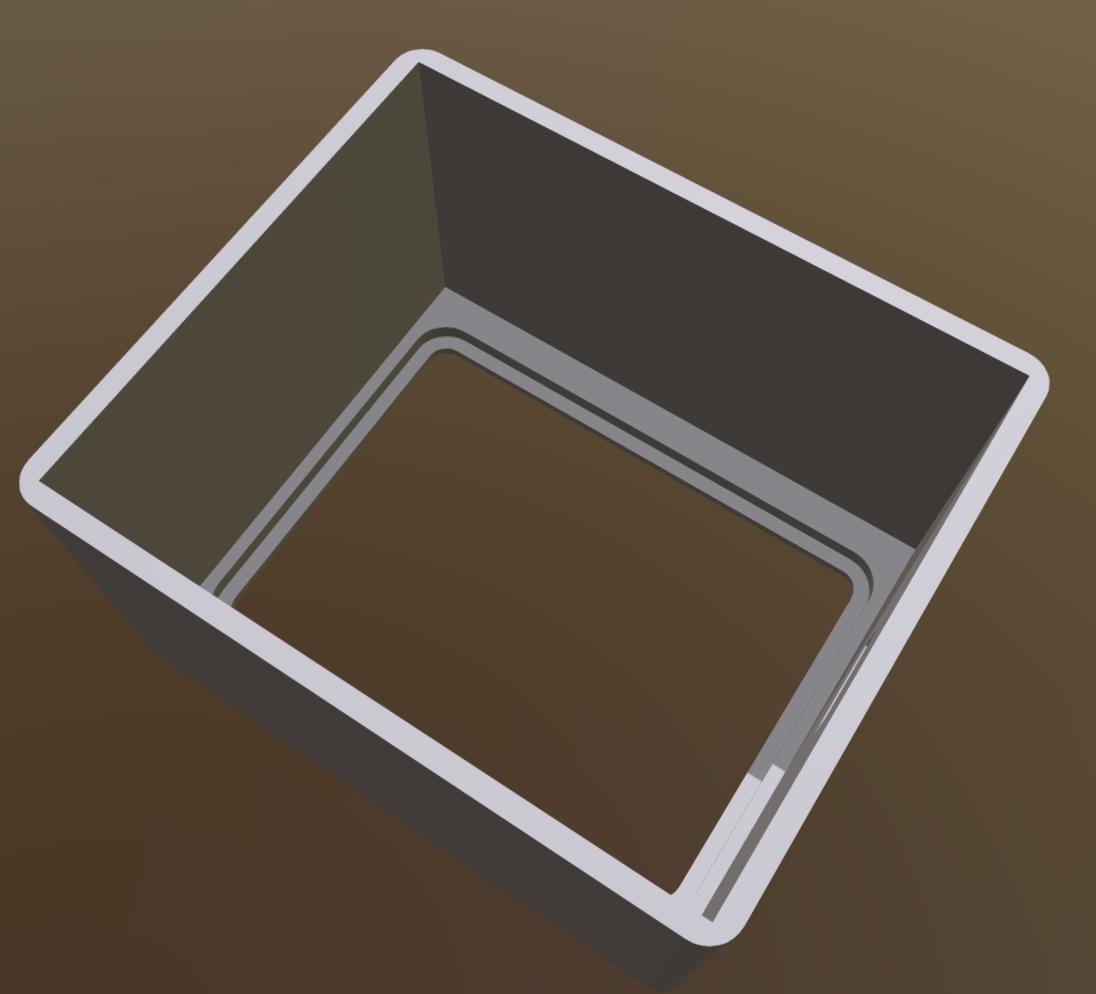
外壳下部
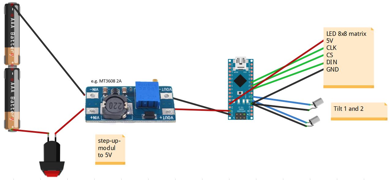
图表
电路
这是我的电路草图。
摇骰代码
/*
Blog-Artikel: Schttel-Wrfel mit LED Matrix und Bewegungssimulation

https://techpluscode.de/schuettel-wuerfel-mit-led-matrix-und-bewegungssimulation/

techpluscode.de
Copyright 2019 von Thomas Angielsky
*/

//Bibliothek fr die Ansteuerung der 8x8 LED-Matrix einbinden
//Include lib for the 8x8 LED matrix
#include "LedControl.h"


int PinTiltX = 2; //Pin fr Tiltsensor X
int PinTiltY = 3; //Pin fr Tiltsensor Y

//Pins der LED-Matrix
//Pins of the LED matrix
int PinCLK = 7;
int PinCS = 6;
int PinDIN = 5;

LedControl lc = LedControl(PinDIN, PinCLK, PinCS, 1);

//Koordinaten der Wrfelaugen in der LED-Matrix
//Coordinates of the Dice points in the LED matrix
int DicePic[8][6][2] =
{
  { //leere Matrix und Startposition:
    {9,9}, //1. Punkt
    {9,8}, //2. Punkt
    {9,7}, //3. Punkt
    {9,6}, //4. Punkt
    {9,5}, //5. Punkt
    {9,4} //6. Punkt
  },
  { //1:
    {4,4}, //1. Punkt
    {-1,-1}, //2. Punkt
    {-1,-1}, //3. Punkt
    {-1,-1}, //4. Punkt
    {-1,-1}, //5. Punkt
    {-1,-1}  //6. Punkt
  },
  { //2:
    {2,2}, //1. Punkt
    {6,6}, //2. Punkt
    {-1,-1}, //3. Punkt
    {-1,-1}, //4. Punkt
    {-1,-1}, //5. Punkt
    {-1,-1}  //6. Punkt
  },
  { //3:
    {2,6}, //1. Punkt
    {6,2}, //2. Punkt
    {4,4}, //3. Punkt
    {-1,-1}, //4. Punkt
    {-1,-1}, //5. Punkt
    {-1,-1}  //6. Punkt
  },
  { //4:
    {2,2}, //1. Punkt
    {2,6}, //2. Punkt
    {6,2}, //3. Punkt
    {6,6}, //4. Punkt
    {-1,-1}, //5. Punkt
    {-1,-1}  //6. Punkt
  },
  { //5:
    {2,2}, //1. Punkt
    {2,6}, //2. Punkt
    {6,2}, //3. Punkt
    {6,6}, //4. Punkt
    {4,4}, //5. Punkt
    {-1,-1}  //6. Punkt
  },
  { //6:
    {2,1}, //1. Punkt
    {2,4}, //2. Punkt
    {2,7}, //3. Punkt
    {6,1}, //4. Punkt
    {6,4}, //5. Punkt
    {6,7}  //6. Punkt
  },
  { //Start:
    {-1,-1}, //1. Punkt
    {-1,-1}, //2. Punkt
    {-1,-1}, //3. Punkt
    {-1,-1}, //4. Punkt
    {-1,-1}, //5. Punkt
    {-1,-1}  //6. Punkt
  }
  };


//Variablen der Wrfelaugen: Position, Richtung, Geschwindigkeit fr X und Y
//Variables of the dice: position, direction, speed for X and Y
float DiceXpos[6];
float DiceXdir[6];
volatile byte DiceXspeed[6];
float DiceYpos[6];
float DiceYdir[6];
volatile byte DiceYspeed[6];


int DiceValue;
unsigned long timestamp;
byte Mode;
int volatile shakes;
int ShakesPerSecond;
int step;

void InterruptChecks() {
  //Schttel-Anzahl zhlen
  //Count Shakes
  shakes=shakes+1;
  //Serial.println(millis());
  timestamp=millis();
}

void SetSpeedX() {
  if (Mode==0) {
    //alle Wrfel in X beschleunigen
    //Speed-up dice in X
    for (int i = 0; i < 6; i++) {
      if (DiceXspeed[i]<255) {DiceXspeed[i]=DiceXspeed[i]+5;}
    }
  }
  InterruptChecks();
}

void SetSpeedY() {
  if (Mode==0) {
    //alle Wrfel in Y beschleunigen
    //Speed-up dice in Y
    for (int i = 0; i < 6; i++) {
      if (DiceYspeed[i]<255) {DiceYspeed[i]=DiceYspeed[i]+5;}
    }
  }
  InterruptChecks();
}

void ShowLed(int x, int y, bool onoff) {
//LED nur anzeigen, wenn im sichtbaren Bereich
//show only, when x/y in matrix
  if ((x<8) and (y<8) and (x>=0) and (y>=0)) {
    lc.setLed(0, x, y, onoff);
  }
}

void ShowDot(int x, int y, bool onoff) {
//Wrfel-Auge anzeigen oder ausblenden
//Show or hide dice point
  ShowLed(x-1, y-1, onoff);
  ShowLed(x, y-1, onoff);
  ShowLed(x-1, y, onoff);
  ShowLed(x, y, onoff);
}

void ShowDicePic(int value) {
//Wurf anzeigen
//Show dice

boolean done;

  //alle Punkte von der aktuellen Position aus zur Zielposition von DiceValue bewegen
  //move all points from current position to destination of DiceValue
  for (int i = 0; i < 6; i++) {
    DiceXspeed[i]=100;
    DiceYspeed[i]=100;

    //Werte fr X berechnen
    //Calc x values
    DiceXdir[i]=0;
    if (int(DiceXpos[i])>DicePic[value][i][0]) {DiceXdir[i]=-1;}
    else if (int(DiceXpos[i])<DicePic[value][i][0]) {DiceXdir[i]=1;}

    DiceYdir[i]=0;
    if (int(DiceYpos[i])>DicePic[value][i][1]) {DiceYdir[i]=-1;}
    else if (int(DiceYpos[i])<DicePic[value][i][1]) {DiceYdir[i]=1;}
  }

  //Serial.println(value);
  //Serial.println("Bewegung Start // Start moving");
  //Punkte bewegen
  do {
    //Serial.println("Bewegung // Moving");
    for (int i = 0; i < 6; i++) {
      if (int(DiceXpos[i])!=DicePic[value][i][0]) {
        DoStep(DiceXpos[i],DiceXdir[i],DiceXspeed[i],false);
      }
      if (int(DiceYpos[i])!=DicePic[value][i][1]) {
        DoStep(DiceYpos[i],DiceYdir[i],DiceYspeed[i],false);
      }
    }

    lc.clearDisplay(0);
    for (int i = 0; i < 6; i++) {
      ShowDot(int(DiceXpos[i]), int(DiceYpos[i]), true);
    }

    delay(50);

    //Sind alle Augen an ihrer Zielposition
    //Dice points are on destition position
    done=true;
    for (int i = 0; i < 6; i++) {
      if (int(DiceXpos[i])!=DicePic[value][i][0]) {done=false;}
      if (int(DiceYpos[i])!=DicePic[value][i][1]) {done=false;}
    }

  } while (done==false);
  //Serial.println("Bewegung Ende // End moving");

  lc.clearDisplay(0);
  for (int i = 0; i < 6; i++) {
    ShowDot(DicePic[value][i][0],DicePic[value][i][1], true);
  }
}


void DoStep(float &pos, float &dir, volatile byte &sp, bool check) {
  pos=pos+float(sp)/255*dir;

  if (check==true) {
    if (pos>7) {
        pos=7;
        dir=dir*(-1);
        }
    if (pos<1) {
        pos=1;
        dir=dir*(-1);
      }

  }
  // Geschwindigkeit wird pro Schritt langsamer
  // Velocity decreases every step
    if (sp>0) {sp=sp-1;}
}

void MoveDots() {
  //alle Wrfel einen Schritt weiter bewegen
  //move dice points one step further
  for (int i = 0; i < 6; i++) {
    //neue Koordinaten berechnen
    //calc new coordinates
    DoStep(DiceXpos[i],DiceXdir[i],DiceXspeed[i],true);
    DoStep(DiceYpos[i],DiceYdir[i],DiceYspeed[i],true);
  }

    //Wrfel-Augen anzeigen
    //show dice points
    lc.clearDisplay(0);
    for (int i = 0; i < 6; i++) {
      ShowDot(int(DiceXpos[i]), int(DiceYpos[i]), true);
    }

}


void setup() {
  //Der MAX7219 ist beim Starten im Power-Saving Modus,
  //er muss aufgeweckt werden.
  //The MAX7219 is in power-saving mode on startup,
  //we have to do a wakeup call
  lc.shutdown(0, false);
  //Helligkeit auf einen Mittelwert
  //Set the brightness to a medium values
  lc.setIntensity(0, 8);
  //und Display lschen
  //and clear the display
  lc.clearDisplay(0);

  randomSeed(analogRead(0));
  DiceValue=0;

  for (int i = 0; i < 6; i++) {
    DiceXpos[i]=DicePic[7][i][0];
    DiceYpos[i]=DicePic[7][i][1];

    DiceXdir[i]=random(3)-1;
    DiceYdir[i]=random(3)-1;
    DiceXspeed[i]=random(126)+120;
    DiceYspeed[i]=random(126)+120;
    }

  //Pins einstellen
  //Setup the pins
  pinMode(PinTiltX, INPUT_PULLUP);
  pinMode(PinTiltY, INPUT_PULLUP);
  attachInterrupt(digitalPinToInterrupt(PinTiltX),SetSpeedX,CHANGE);
  attachInterrupt(digitalPinToInterrupt(PinTiltY),SetSpeedY,CHANGE);

  lc.clearDisplay(0);

  timestamp=millis();
  Mode=1;

  ShowDicePic(6);
  delay(1000);

  lc.clearDisplay(0);
  Mode=0;
  Serial.begin(9600);
  step=0;
  shakes=0;
}

void loop() {
  delay(50);
  step=step+1;
  if (step>20) {
    //1 sek ist vorbei
    //1 sec is over
    step=0;
    ShakesPerSecond=shakes;
    shakes=0;
  }

  if (Mode==0) {
    MoveDots();
    if (millis()-timestamp>2000) {
      //seit 2 sek kein Schtteln mehr
      //there is no shaking since 2 sec
      Mode=1;
      DiceValue=random(6)+1;
      ShowDicePic(DiceValue);
    }
  }

  if (ShakesPerSecond>5) {
    //Es wird wieder geschttelt
    //shaking again
    Mode=0;
  }

}
附录
项目链接:https://www.hackster.io/tangielsky/shaking-arduino-dice-39fc6a
项目作者:德国 托马斯·安吉尔斯基
(机械工程师、制造商,喜欢木工,就像 Lazarus 一样)
3D打印文件:https://hacksterio.s3.amazonaws.com/uploads/attachments/727032/oberteil_ehbbTeKHvI.stl


 他的勋章
他的勋章

评论