37款传感器与执行器的提法,在网络上广泛流传,其实Arduino能够兼容的传感器模块肯定是不止这37种的。鉴于本人手头积累了一些传感器和执行器模块,依照实践出真知(一定要动手做)的理念,以学习和交流为目的,这里准备逐一动手尝试系列实验,不管成功(程序走通)与否,都会记录下来—小小的进步或是搞不掂的问题,希望能够抛砖引玉。
【Arduino】168种传感器模块系列实验(资料代码+仿真编程+图形编程)
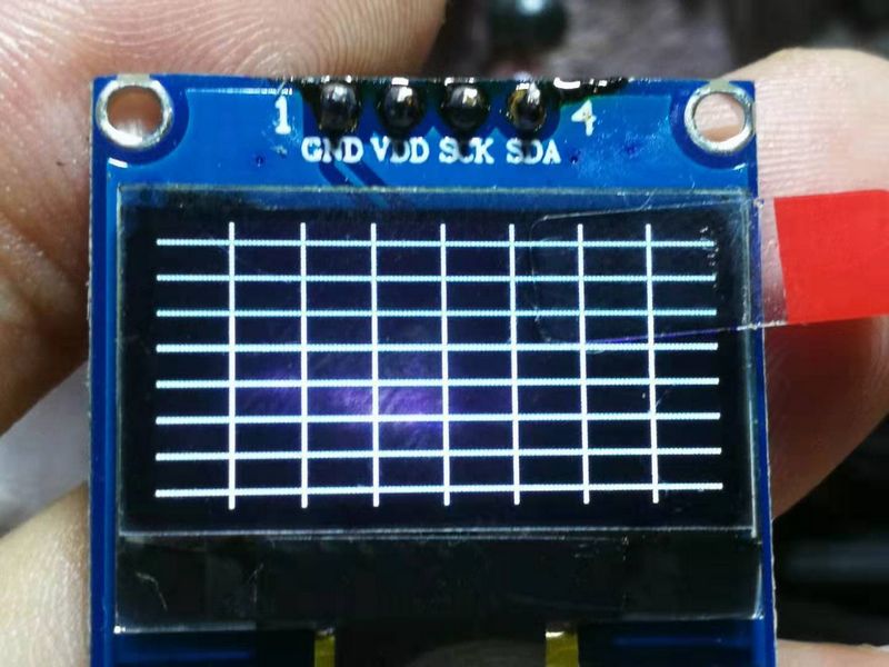
实验九十三:0.96寸I2C IIC通信128*64显示器 OLED液晶屏模块
【Arduino】168种传感器模块系列实验(资料代码+图形编程+仿真编程)
实验九十三: 0.96寸I2C IIC通信128*64显示器 OLED液晶屏模块
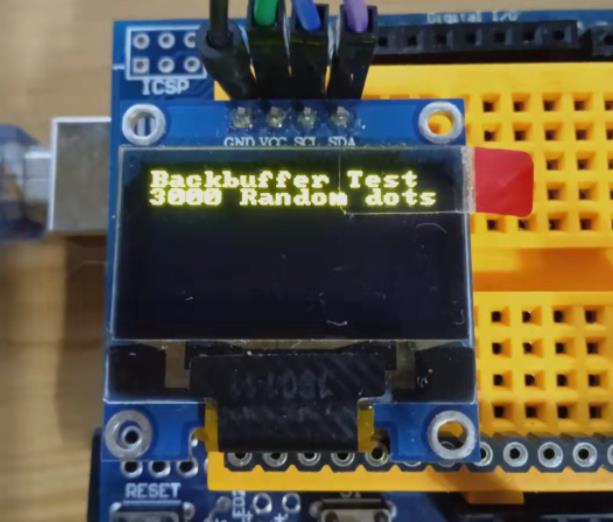
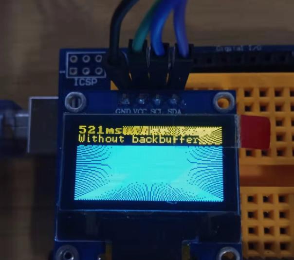
项目四十二:显示文字与绘图渲染
实验开源代码
/*
  【Arduino】168种传感器模块系列实验(资料代码+图形编程+仿真编程)
  实验九十七: 0.96寸I2C IIC通信128*64显示器 OLED液晶屏模块
  项目四十二:显示文字与绘图渲染
  实验接线:
  oled模块    Ardunio Uno
  GND---------GND接地线
  VCC---------5V 接电源
  SDA---------A4
  SCL ------- A5
*/

#include <OneBitDisplay.h>

// if your system doesn't have enough RAM for a back buffer, comment out
// this line (e.g. ATtiny85)
#define USE_BACKBUFFER

#ifdef USE_BACKBUFFER
static uint8_t ucBackBuffer[1024];
#else
static uint8_t *ucBackBuffer = NULL;
#endif

// Use -1 for the Wire library default pins
// or specify the pin numbers to use with the Wire library or bit banging on any GPIO pins
// These are the pin numbers for the M5Stack Atom Grove port I2C (reversed SDA/SCL for straight through wiring)
#define SDA_PIN A4
#define SCL_PIN A5
// Set this to -1 to disable or the GPIO pin number connected to the reset
// line of your display if it requires an external reset
#define RESET_PIN -1
// let OneBitDisplay figure out the display address
#define OLED_ADDR -1
// don't rotate the display
#define FLIP180 0
// don't invert the display
#define INVERT 0
// Bit-Bang the I2C bus
#define USE_HW_I2C 1

// Change these if you're using a different OLED display
#define MY_OLED OLED_128x64
#define OLED_WIDTH 128
#define OLED_HEIGHT 64
//#define MY_OLED OLED_64x32
//#define OLED_WIDTH 64
//#define OLED_HEIGHT 32

OBDISP obd;

void setup() {
int rc;
// The I2C SDA/SCL pins set to -1 means to use the default Wire library
// If pins were specified, they would be bit-banged in software
// This isn't inferior to hw I2C and in fact allows you to go faster on certain CPUs
// The reset pin is optional and I've only seen it needed on larger OLEDs (2.4")
//    that can be configured as either SPI or I2C
//
// obdI2CInit(OBDISP *, type, oled_addr, rotate180, invert, bWire, SDA_PIN, SCL_PIN, RESET_PIN, speed)

rc = obdI2CInit(&obd, MY_OLED, OLED_ADDR, FLIP180, INVERT, USE_HW_I2C, SDA_PIN, SCL_PIN, RESET_PIN, 800000L); // use standard I2C bus at 400Khz
  if (rc != OLED_NOT_FOUND)
  {
    char *msgs[] = {(char *)"SSD1306 @ 0x3C", (char *)"SSD1306 @ 0x3D",(char *)"SH1106 @ 0x3C",(char *)"SH1106 @ 0x3D"};
    obdFill(&obd, 0, 1);
    obdWriteString(&obd, 0,0,0,msgs[rc], FONT_8x8, 0, 1);
    obdSetBackBuffer(&obd, ucBackBuffer);
    delay(2000);
  }
} /* setup() */

void loop() {
  // put your main code here, to run repeatedly:
int i, x, y;
char szTemp[32];
unsigned long ms;

  obdFill(&obd, 0x0, 1);
  obdWriteString(&obd, 0,28,0,(char *)"OLED Demo", FONT_8x8, 0, 1);
  obdWriteString(&obd, 0,0,1,(char *)"Written by Larry Bank", FONT_6x8, 1, 1);
  obdWriteString(&obd, 0,0,3,(char *)"**Demo**", FONT_16x32, 0, 1);
  delay(2000);

 // Pixel and line functions won't work without a back buffer
#ifdef USE_BACKBUFFER
  obdFill(&obd, 0, 1);
  obdWriteString(&obd, 0,0,0,(char *)"Backbuffer Test", FONT_8x8,0,1);
  obdWriteString(&obd, 0,0,1,(char *)"3000 Random dots", FONT_8x8,0,1);
  delay(2000);
  obdFill(&obd, 0,1);
  ms = millis();
  for (i=0; i<3000; i++)
  {
    x = random(OLED_WIDTH);
    y = random(OLED_HEIGHT);
    obdSetPixel(&obd, x, y, 1, 1);
  }
  ms = millis() - ms;
  sprintf(szTemp, "%dms", (int)ms);
  obdWriteString(&obd, 0,0,0,szTemp, FONT_8x8, 0, 1);
  obdWriteString(&obd, 0,0,1,(char *)"Without backbuffer", FONT_6x8,0,1);
  delay(2000);
  obdFill(&obd, 0,1);
  ms = millis();
  for (i=0; i<3000; i++)
  {
    x = random(OLED_WIDTH);
    y = random(OLED_HEIGHT);
    obdSetPixel(&obd, x, y, 1, 0);
  }
  obdDumpBuffer(&obd, NULL);
  ms = millis() - ms;
  sprintf(szTemp, "%dms", (int)ms);
  obdWriteString(&obd, 0,0,0,szTemp, FONT_8x8, 0, 1);
  obdWriteString(&obd, 0,0,1,(char *)"With backbuffer", FONT_6x8,0,1);
  delay(2000);
  obdFill(&obd, 0, 1);
  obdWriteString(&obd, 0,0,0,(char *)"Backbuffer Test", FONT_8x8,0,1);
  obdWriteString(&obd, 0,0,1,(char *)"96 lines", FONT_8x8,0,1);
  delay(2000);
  ms = millis();
  for (x=0; x<OLED_WIDTH-1; x+=2)
  {
    obdDrawLine(&obd, x, 0, OLED_WIDTH-x, OLED_HEIGHT-1, 1, 1);
  }
  for (y=0; y<OLED_HEIGHT-1; y+=2)
  {
    obdDrawLine(&obd, OLED_WIDTH-1,y, 0,OLED_HEIGHT-1-y, 1, 1);
  }
  ms = millis() - ms;
  sprintf(szTemp, "%dms", (int)ms);
  obdWriteString(&obd, 0,0,0,szTemp, FONT_8x8, 0, 1);
  obdWriteString(&obd, 0,0,1,(char *)"Without backbuffer", FONT_6x8,0,1);
  delay(2000);
  obdFill(&obd, 0,1);
  ms = millis();
  for (x=0; x<OLED_WIDTH-1; x+=2)
  {
    obdDrawLine(&obd, x, 0, OLED_WIDTH-1-x, OLED_HEIGHT-1, 1, 0);
  }
  for (y=0; y<OLED_HEIGHT-1; y+=2)
  {
    obdDrawLine(&obd, OLED_WIDTH-1,y, 0,OLED_HEIGHT-1-y, 1, 0);
  }
  obdDumpBuffer(&obd, ucBackBuffer);
  ms = millis() - ms;
  sprintf(szTemp, "%dms", (int)ms);
  obdWriteString(&obd, 0,0,0,szTemp, FONT_8x8, 0, 1);
  obdWriteString(&obd, 0,0,1,(char *)"With backbuffer", FONT_6x8,0,1);
  delay(2000);
#endif
} /* loop() */
Arduino实验场景图
【Arduino】168种传感器模块系列实验(资料代码+图形编程+仿真编程)
实验九十三: 0.96寸I2C IIC通信128*64显示器 OLED液晶屏模块
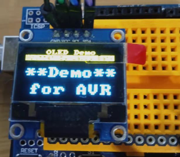
项目四十三:AVR 平台 OneBitDisplay 库的标准使用
实验开源代码
/*
  【Arduino】168种传感器模块系列实验(资料代码+图形编程+仿真编程)
  实验九十七: 0.96寸I2C IIC通信128*64显示器 OLED液晶屏模块
  项目四十三:AVR 平台 OneBitDisplay 库的标准使用
  实验接线:
  oled模块    Ardunio Uno
  GND---------GND接地线
  VCC---------5V 接电源
  SDA---------A4
  SCL ------- A5
*/

#include <OneBitDisplay.h>

OBDISP obd;
#define SDA_PIN -1
#define SCL_PIN -1
// no reset pin needed
#define RESET_PIN -1
// let OneBitDisplay find the address of our display
#define OLED_ADDR -1
#define FLIP180 0
#define INVERT 0
// Use the default Wire library
#define USE_HW_I2C 1
void setup()
{
    int rc;
    rc = obdI2CInit(&obd, OLED_128x64, OLED_ADDR, FLIP180, INVERT, USE_HW_I2C, SDA_PIN, SCL_PIN, RESET_PIN, 400000L);       // Standard HW I2C bus at 400Khz

    if (rc != OLED_NOT_FOUND)
    {
        char *msgs[] =
        {
          (char *)"SSD1306 @ 0x3C",
          (char *)"SSD1306 @ 0x3D",
          (char *)"SH1106 @ 0x3C",
          (char *)"SH1106 @ 0x3D"
        };

        obdFill(&obd, 0, 1);
        obdWriteString(&obd, 0, 0, 0, (char *)"OLED found:", FONT_8x8, 0, 1);
        obdWriteString(&obd, 0, 10, 2, msgs[rc], FONT_8x8, 0, 1);
        delay(3000);
    }
}

void loop()
{
    int i, x, y;

    obdFill(&obd, 0, 1);
    obdWriteString(&obd, 0, 28, 0,(char *)"OLED Demo", FONT_8x8, 0, 1);
    obdWriteString(&obd, 0, 0, 1,(char *)"Written by Larry Bank", FONT_6x8, 1, 1);
    obdWriteString(&obd, 0, 0, 3,(char *)"**Demo**", FONT_16x16, 0, 1);
    obdWriteString(&obd, 0, 9, 6,(char *)"for AVR", FONT_16x16, 0, 1);

    delay(2000);
    obdFill(&obd, 0, 1);

    for (i = 0; i < 1000; i++)
    {
        x = random(128);
        y = random(64);
        obdSetPixel(&obd, x, y, 1, 1);
    }

    delay(2000);
}
Arduino实验场景图
【Arduino】168种传感器模块系列实验(资料代码+图形编程+仿真编程)
实验九十三: 0.96寸I2C IIC通信128*64显示器 OLED液晶屏模块
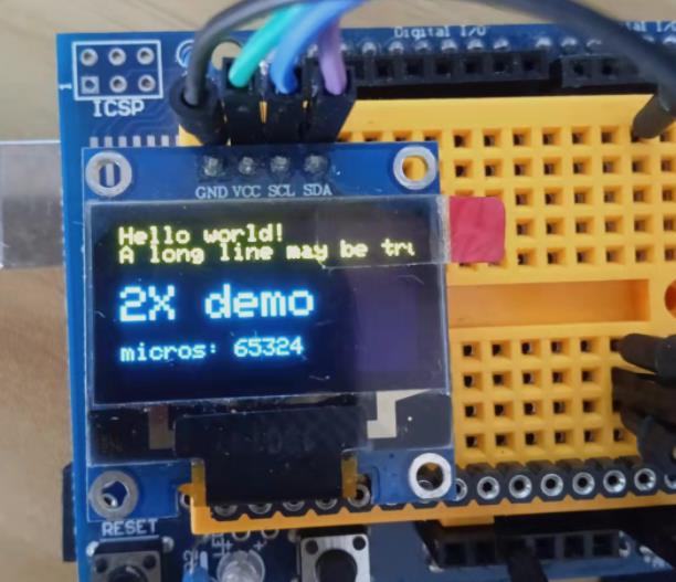
项目四十四:使用更小更快的 AvrI2c 类代替 Wire
实验开源代码
/*
  【Arduino】168种传感器模块系列实验(资料代码+图形编程+仿真编程)
  实验九十七: 0.96寸I2C IIC通信128*64显示器 OLED液晶屏模块
  项目四十四:使用更小更快的 AvrI2c 类代替 Wire
  实验接线:
  oled模块    Ardunio Uno
  GND---------GND接地线
  VCC---------5V 接电源
  SDA---------A4
  SCL ------- A5
*/

#include "SSD1306Ascii.h"
#include "SSD1306AsciiAvrI2c.h"

// 0X3C+SA0 - 0x3C or 0x3D
#define I2C_ADDRESS 0x3C

// Define proper RST_PIN if required.
#define RST_PIN -1

SSD1306AsciiAvrI2c oled;
/
void setup() {

#if RST_PIN >= 0
  oled.begin(&Adafruit128x64, I2C_ADDRESS, RST_PIN);
#else // RST_PIN >= 0
  oled.begin(&Adafruit128x64, I2C_ADDRESS);
#endif // RST_PIN >= 0
  // 调用 oled.setI2cClock(frequency) 来改变默认频率。
  oled.setFont(Adafruit5x7);

  uint32_t m = micros();
  oled.clear();
  oled.println("Hello world!");
  oled.println("A long line may be truncated");
  oled.println();
  oled.set2X();
  oled.println("2X demo");
  oled.set1X();
  oled.print("\nmicros: ");
  oled.print(micros() - m);
}
void loop() {}
Arduino实验场景图

 返回首页
返回首页
 回到顶部
回到顶部


9mm2023.07.27
666