 返回首页
返回首页
 回到顶部
回到顶部
接上集
已经完成了扩展板及相关电路的焊接工作,并且在pico-SDK的开发环境下测试了RP2350与板载的AHT20通信是否正常,接下来开始制作VC02的固件、OLED屏幕的驱动以及RP2350串口接收等程序的编写验证。
硬件连接
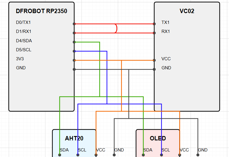
基本的硬件连接如图所示,RP2350作为主控分别连接VC02、AHT20以及OLED显示屏,其中VC02负责和用户语音交互,同时根据不同指令输出不同的命令,RP2350处理命令并且显示在OLED上,实现语音交互等功能。
代码
OLED源代码
/**
* SSD1306 OLED Driver for Raspberry Pi Pico
* Displaying dynamic facial expressions (128x64)
*/
#include
#include
#include
#include "pico/stdlib.h"
#include "pico/binary_info.h"
#include "hardware/i2c.h"
#include
#include "oled.h"
#define SSD1306_I2C_CLK 400
// I2C port configuration
#define I2C_PORT i2c0
#define I2C_SDA 4
#define I2C_SCL 5
void calc_render_area_buflen(struct render_area *area) {
// calculate how long the flattened buffer will be for a render area
area->buflen = (area->end_col - area->start_col + 1) * (area->end_page - area->start_page + 1);
}
void SSD1306_send_cmd(uint8_t cmd) {
// I2C write process expects a control byte followed by data
// this "data" can be a command or data to follow up a command
// Co = 1, D/C = 0 => the driver expects a command
uint8_t buf[2] = {0x80, cmd};
i2c_write_blocking(I2C_PORT, SSD1306_I2C_ADDR, buf, 2, false);
}
void SSD1306_send_cmd_list(uint8_t *buf, int num) {
for (int i = 0; i < num; i++)
SSD1306_send_cmd(buf[i]);
}
void SSD1306_send_buf(uint8_t buf[], int buflen) {
// in horizontal addressing mode, the column address pointer auto-increments
// and then wraps around to the next page
// copy our frame buffer into a new buffer because we need to add the control byte
// to the beginning
uint8_t *temp_buf = malloc(buflen + 1);
temp_buf[0] = 0x40;
memcpy(temp_buf+1, buf, buflen);
i2c_write_blocking(I2C_PORT, SSD1306_I2C_ADDR, temp_buf, buflen + 1, false);
free(temp_buf);
}
void SSD1306_init() {
// Some of these commands are not strictly necessary as the reset
// process defaults to some of these but they are shown here
// to demonstrate what the initialization sequence looks like
uint8_t cmds[] = {
SSD1306_SET_DISP, // set display off
/* memory mapping */
SSD1306_SET_MEM_MODE, // set memory address mode 0 = horizontal, 1 = vertical, 2 = page
0x00, // horizontal addressing mode
/* resolution and layout */
SSD1306_SET_DISP_START_LINE, // set display start line to 0
SSD1306_SET_SEG_REMAP | 0x01, // set segment re-map, column address 127 is mapped to SEG0
SSD1306_SET_MUX_RATIO, // set multiplex ratio
SSD1306_HEIGHT - 1, // Display height - 1
SSD1306_SET_COM_OUT_DIR | 0x08, // set COM (common) output scan direction. Scan from bottom up, COM[N-1] to COM0
SSD1306_SET_DISP_OFFSET, // set display offset
0x00, // no offset
SSD1306_SET_COM_PIN_CFG, // set COM (common) pins hardware configuration
0x12, // Appropriate for 128x64 display
/* timing and driving scheme */
SSD1306_SET_DISP_CLK_DIV, // set display clock divide ratio
0x80, // div ratio of 1, standard freq
SSD1306_SET_PRECHARGE, // set pre-charge period
0xF1, // Vcc internally generated on our board
SSD1306_SET_VCOM_DESEL, // set VCOMH deselect level
0x30, // 0.83xVcc
/* display */
SSD1306_SET_CONTRAST, // set contrast control
0xFF,
SSD1306_SET_ENTIRE_ON, // set entire display on to follow RAM content
SSD1306_SET_NORM_DISP, // set normal (not inverted) display
SSD1306_SET_CHARGE_PUMP, // set charge pump
0x14, // Vcc internally generated on our board
SSD1306_SET_SCROLL | 0x00, // deactivate horizontal scrolling if set
SSD1306_SET_DISP | 0x01, // turn display on
};
SSD1306_send_cmd_list(cmds, sizeof(cmds));
}
void render(uint8_t *buf, struct render_area *area) {
// update a portion of the display with a render area
uint8_t cmds[] = {
SSD1306_SET_COL_ADDR,
area->start_col,
area->end_col,
SSD1306_SET_PAGE_ADDR,
area->start_page,
area->end_page
};
SSD1306_send_cmd_list(cmds, sizeof(cmds));
SSD1306_send_buf(buf, area->buflen);
}
void SetPixel(uint8_t *buf, int x, int y, bool on) {
if (x >= 0 && x < SSD1306_WIDTH && y >= 0 && y < SSD1306_HEIGHT) {
// The calculation to determine the correct bit to set depends on which address
// mode we are in. This code assumes horizontal
// The video ram on the SSD1306 is split up in to 8 rows, one bit per pixel.
// Each row is 128 long by 8 pixels high, each byte vertically arranged, so byte 0 is x=0, y=0->7,
// byte 1 is x = 1, y=0->7 etc
const int BytesPerRow = SSD1306_WIDTH; // x pixels, 1bpp, but each row is 8 pixel high
int byte_idx = (y / 8) * BytesPerRow + x;
uint8_t byte = buf[byte_idx];
if (on)
byte |= 1 << (y % 8);
else
byte &= ~(1 << (y % 8));
buf[byte_idx] = byte;
}
}
// Basic Bresenhams.
void DrawLine(uint8_t *buf, int x0, int y0, int x1, int y1, bool on) {
int dx = abs(x1-x0);
int sx = x0
int dy = -abs(y1-y0);
int sy = y0
int err = dx+dy;
int e2;
while (true) {
SetPixel(buf, x0, y0, on);
if (x0 == x1 && y0 == y1)
break;
e2 = 2*err;
if (e2 >= dy) {
err += dy;
x0 += sx;
}
if (e2 <= dx) {
err += dx;
y0 += sy;
}
}
}
void DrawCircle(uint8_t *buf, int xc, int yc, int r, bool on) {
// Bresenham's circle drawing algorithm
int x = 0;
int y = r;
int d = 3 - 2 * r;
while (y >= x) {
// Draw 8 octants
SetPixel(buf, xc + x, yc + y, on);
SetPixel(buf, xc - x, yc + y, on);
SetPixel(buf, xc + x, yc - y, on);
SetPixel(buf, xc - x, yc - y, on);
SetPixel(buf, xc + y, yc + x, on);
SetPixel(buf, xc - y, yc + x, on);
SetPixel(buf, xc + y, yc - x, on);
SetPixel(buf, xc - y, yc - x, on);
x++;
if (d > 0) {
y--;
d = d + 4 * (x - y) + 10;
} else {
d = d + 4 * x + 6;
}
}
}
// Draw a filled circle
void FillCircle(uint8_t *buf, int xc, int yc, int r, bool on) {
// Draw filled circle by drawing horizontal lines
for (int y = -r; y <= r; y++) {
int x_bound = (int)sqrt(r*r - y*y);
for (int x = -x_bound; x <= x_bound; x++) {
SetPixel(buf, xc + x, yc + y, on);
}
}
}
// Draw face functions
void DrawHappyFace(uint8_t *buf) {
// Clear buffer
memset(buf, 0, SSD1306_BUF_LEN);
// Draw face outline
DrawCircle(buf, 64, 32, 25, true);
// Draw eyes
FillCircle(buf, 52, 24, 4, true);
FillCircle(buf, 76, 24, 4, true);
// Draw smile (arc)
for (int x = 50; x <= 78; x++) {
int y = 42 - (int)(5.0 * sin((x - 50) * 3.14159 / 28.0));
SetPixel(buf, x, y, true);
SetPixel(buf, x, y+1, true);
}
}
void DrawSadFace(uint8_t *buf) {
// Clear buffer
memset(buf, 0, SSD1306_BUF_LEN);
// Draw face outline
DrawCircle(buf, 64, 32, 25, true);
// Draw eyes
FillCircle(buf, 52, 24, 4, true);
FillCircle(buf, 76, 24, 4, true);
// Draw frown (arc)
for (int x = 50; x <= 78; x++) {
int y = 46 + (int)(5.0 * sin((x - 50) * 3.14159 / 28.0));
SetPixel(buf, x, y, true);
SetPixel(buf, x, y+1, true);
}
}
void DrawNeutralFace(uint8_t *buf) {
// Clear buffer
memset(buf, 0, SSD1306_BUF_LEN);
// Draw face outline
DrawCircle(buf, 64, 32, 25, true);
// Draw eyes
FillCircle(buf, 52, 24, 4, true);
FillCircle(buf, 76, 24, 4, true);
// Draw neutral mouth (line)
DrawLine(buf, 50, 45, 78, 45, true);
DrawLine(buf, 50, 46, 78, 46, true);
}
#define COUNT_OF(x) (sizeof(x) / sizeof((x)[0]))
OLED头文件
/**
* SSD1306 OLED Driver Header
* For Raspberry Pi Pico
*
* This header file provides functions to control SSD1306 OLED displays
* and draw facial expressions
*/
#ifndef SSD1306_OLED_H
#define SSD1306_OLED_H
#include
#include
// Define the size of the display
#define SSD1306_HEIGHT 64
#define SSD1306_WIDTH 128
#define SSD1306_I2C_ADDR 0x3C
#define SSD1306_I2C_CLK 400
// I2C port configuration - can be overridden in your main program
#ifndef I2C_PORT
#define I2C_PORT i2c0
#endif
#ifndef I2C_SDA
#define I2C_SDA 4
#endif
#ifndef I2C_SCL
#define I2C_SCL 5
#endif
// Display page information
#define SSD1306_PAGE_HEIGHT 8
#define SSD1306_NUM_PAGES (SSD1306_HEIGHT / SSD1306_PAGE_HEIGHT)
#define SSD1306_BUF_LEN (SSD1306_NUM_PAGES * SSD1306_WIDTH)
/**
* Render area structure
* Defines a rectangle on the OLED display for rendering
*/
struct render_area {
uint8_t start_col;
uint8_t end_col;
uint8_t start_page;
uint8_t end_page;
int buflen;
};
/**
* Calculate the buffer length required for a render area
*
* @param area The render area to calculate buffer length for
*/
void calc_render_area_buflen(struct render_area *area);
/**
* Send a command to the SSD1306 OLED display
*
* @param cmd The command byte to send
*/
void SSD1306_send_cmd(uint8_t cmd);
/**
* Send multiple commands to the SSD1306 OLED display
*
* @param buf Array of command bytes
* @param num Number of commands in the array
*/
void SSD1306_send_cmd_list(uint8_t *buf, int num);
/**
* Send a buffer of data to the SSD1306 OLED display
*
* @param buf The data buffer to send
* @param buflen The length of the data buffer
*/
void SSD1306_send_buf(uint8_t buf[], int buflen);
/**
* Initialize the SSD1306 OLED display
*/
void SSD1306_init(void);
/**
* Render data to a specific area of the OLED display
*
* @param buf The data buffer to render
* @param area The area to render to
*/
void render(uint8_t *buf, struct render_area *area);
/**
* Set a single pixel in the buffer
*
* @param buf The data buffer
* @param x X coordinate (0 to SSD1306_WIDTH-1)
* @param y Y coordinate (0 to SSD1306_HEIGHT-1)
* @param on true to set pixel, false to clear
*/
void SetPixel(uint8_t *buf, int x, int y, bool on);
/**
* Draw a line between two points
*
* @param buf The data buffer
* @param x0 Start X coordinate
* @param y0 Start Y coordinate
* @param x1 End X coordinate
* @param y1 End Y coordinate
* @param on true to draw line, false to erase
*/
void DrawLine(uint8_t *buf, int x0, int y0, int x1, int y1, bool on);
/**
* Draw a circle outline
*
* @param buf The data buffer
* @param xc Center X coordinate
* @param yc Center Y coordinate
* @param r Radius
* @param on true to draw circle, false to erase
*/
void DrawCircle(uint8_t *buf, int xc, int yc, int r, bool on);
/**
* Draw a filled circle
*
* @param buf The data buffer
* @param xc Center X coordinate
* @param yc Center Y coordinate
* @param r Radius
* @param on true to draw filled circle, false to erase
*/
void FillCircle(uint8_t *buf, int xc, int yc, int r, bool on);
/**
* Draw a happy face emoji
*
* @param buf The data buffer
*/
void DrawHappyFace(uint8_t *buf);
/**
* Draw a sad face emoji
*
* @param buf The data buffer
*/
void DrawSadFace(uint8_t *buf);
/**
* Draw a neutral face emoji
*
* @param buf The data buffer
*/
void DrawNeutralFace(uint8_t *buf);
/**
* Command definitions for SSD1306
*/
#define SSD1306_SET_MEM_MODE 0x20
#define SSD1306_SET_COL_ADDR 0x21
#define SSD1306_SET_PAGE_ADDR 0x22
#define SSD1306_SET_HORIZ_SCROLL 0x26
#define SSD1306_SET_SCROLL 0x2E
#define SSD1306_SET_DISP_START_LINE 0x40
#define SSD1306_SET_CONTRAST 0x81
#define SSD1306_SET_CHARGE_PUMP 0x8D
#define SSD1306_SET_SEG_REMAP 0xA0
#define SSD1306_SET_ENTIRE_ON 0xA4
#define SSD1306_SET_ALL_ON 0xA5
#define SSD1306_SET_NORM_DISP 0xA6
#define SSD1306_SET_INV_DISP 0xA7
#define SSD1306_SET_MUX_RATIO 0xA8
#define SSD1306_SET_DISP 0xAE
#define SSD1306_SET_COM_OUT_DIR 0xC0
#define SSD1306_SET_COM_OUT_DIR_FLIP 0xC0
#define SSD1306_SET_DISP_OFFSET 0xD3
#define SSD1306_SET_DISP_CLK_DIV 0xD5
#define SSD1306_SET_PRECHARGE 0xD9
#define SSD1306_SET_COM_PIN_CFG 0xDA
#define SSD1306_SET_VCOM_DESEL 0xDB
#define SSD1306_WRITE_MODE 0xFE
#define SSD1306_READ_MODE 0xFF
#endif /* SSD1306_OLED_H */
主函数源代码
#include
#include "pico/stdlib.h"
#include "pico/binary_info.h"
#include "hardware/spi.h"
#include "hardware/i2c.h"
#include "hardware/uart.h"
#include "aht20.h"
#include "gc9a01.h"
#include "oled.h"
#include
#include "hardware/irq.h"
// SPI Defines
// We are going to use SPI 0, and allocate it to the following GPIO pins
// Pins can be changed, see the GPIO function select table in the datasheet for information on GPIO assignments
#define SPI_PORT spi0
#define PIN_SCK 18
#define PIN_MOSI 19
// I2C defines
// This example will use I2C0 on GPIO8 (SDA) and GPIO9 (SCL) running at 400KHz.
// Pins can be changed, see the GPIO function select table in the datasheet for information on GPIO assignments
#define I2C_PORT i2c0
#define I2C_SDA 4
#define I2C_SCL 5
// UART defines
// By default the stdout UART is `uart0`, so we will use the second one
#define UART_ID uart0
#define BAUD_RATE 115200
// Use pins 4 and 5 for UART1
// Pins can be changed, see the GPIO function select table in the datasheet for information on GPIO assignments
#define UART_TX_PIN 0
#define UART_RX_PIN 1
#define DATA_BITS 8
#define STOP_BITS 1
#define PARITY UART_PARITY_NONE
// 指令缓冲区设置
#define COMMAND_SIZE 5
static uint8_t rx_buffer[COMMAND_SIZE];
static int buffer_index = 0;
static int chars_rxed = 0;
uint8_t smile_flag=0;
uint8_t cry_flag=0;
// Display dimensions (GC9A01 is 240x240)
#define DISPLAY_WIDTH 240
#define DISPLAY_HEIGHT 240
// Simple function to fill screen with a color
void fill_screen(uint16_t color) {
uint8_t hi = color >> 8;
uint8_t lo = color & 0xFF;
// Convert to RGB666 format
uint8_t r = (hi & 0xF8) >> 3; // 5 bits
uint8_t g = ((hi & 0x07) << 3) | ((lo & 0xE0) >> 5); // 6 bits
uint8_t b = lo & 0x1F; // 5 bits
// Convert to RGB888 format for 18-bit color
uint8_t rgb[3];
rgb[0] = (r << 3) | (r >> 2); // Expand 5 bits to 8 bits
rgb[1] = (g << 2) | (g >> 4); // Expand 6 bits to 8 bits
rgb[2] = (b << 3) | (b >> 2); // Expand 5 bits to 8 bits
// Set drawing frame to entire screen
struct GC9A01_frame frame = {
.start = {0, 0},
.end = {DISPLAY_WIDTH-1, DISPLAY_HEIGHT-1}
};
GC9A01_set_frame(frame);
// Write first pixel
GC9A01_write(rgb, 3);
// Fill remaining pixels
for (int i = 1; i < DISPLAY_WIDTH * DISPLAY_HEIGHT; i++) {
GC9A01_write_continue(rgb, 3);
}
}
// Draw a colorful test pattern
void draw_test_pattern() {
// Set drawing frame to entire screen
struct GC9A01_frame frame = {
.start = {0, 0},
.end = {DISPLAY_WIDTH-1, DISPLAY_HEIGHT-1}
};
GC9A01_set_frame(frame);
// Start memory write
GC9A01_write_command(0x2C);
// Write pixel data
for (int y = 0; y < DISPLAY_HEIGHT; y++) {
for (int x = 0; x < DISPLAY_WIDTH; x++) {
uint8_t r = x / (DISPLAY_WIDTH / 32);
uint8_t g = y / (DISPLAY_HEIGHT / 32);
uint8_t b = 31 - (x+y) / ((DISPLAY_WIDTH+DISPLAY_HEIGHT) / 64);
// Convert to RGB888 format for 18-bit color
uint8_t rgb[3];
rgb[0] = (r << 3) | (r >> 2); // Expand 5 bits to 8 bits
rgb[1] = (g << 2) | (g >> 4); // Expand 6 bits to 8 bits
rgb[2] = (b << 3) | (b >> 2); // Expand 5 bits to 8 bits
GC9A01_set_data_command(1);
GC9A01_spi_tx(rgb, 3);
}
}
}
// 处理接收到的完整指令
void process_command(uint8_t* cmd) {
// 检查第一个指令: 0x5a 0x00 0x00 0x00 0x5a
if (cmd[0] == 0x5A && cmd[1] == 0x00 && cmd[2] == 0x00 &&
cmd[3] == 0x00 && cmd[4] == 0x5A) {
printf("收到指令1: 0x5A 0x00 0x00 0x00 0x5A\n");
// 在这里添加指令1的处理逻辑
// 例如:控制LED、读取传感器等
smile_flag=1;
}
// 检查第二个指令: 0x5a 0x01 0x00 0x00 0x5b
else if (cmd[0] == 0x5A && cmd[1] == 0x01 && cmd[2] == 0x00 &&
cmd[3] == 0x00 && cmd[4] == 0x5B) {
printf("收到指令2: 0x5A 0x01 0x00 0x00 0x5B\n");
// 在这里添加指令2的处理逻辑
// 例如:改变工作模式、发送数据等
cry_flag=1;
}
else {
printf("未知指令\n");
}
}
// RX中断处理程序
void on_uart_rx() {
while (uart_is_readable(UART_ID)) {
uint8_t ch = uart_getc(UART_ID);
// 将接收到的字节存储在缓冲区中
rx_buffer[buffer_index] = ch;
buffer_index++;
chars_rxed++;
// 如果缓冲区已满,处理命令
if (buffer_index >= COMMAND_SIZE) {
process_command(rx_buffer);
buffer_index = 0; // 重置缓冲区索引
}
}
}
int main()
{
stdio_init_all();
i2c_init(I2C_PORT, 400*1000);
gpio_set_function(I2C_SDA, GPIO_FUNC_I2C);
gpio_set_function(I2C_SCL, GPIO_FUNC_I2C);
gpio_pull_up(I2C_SDA);
gpio_pull_up(I2C_SCL);
sleep_ms(10000);
printf("Initializing AHT20 sensor...\n");
// 创建AHT20数据结构并初始化传感器
AHT20_data_t aht20_data = {0};
int result = AHT20_begin(&aht20_data);
if (result != 0) {
printf("Failed to initialize AHT20 sensor! Error code: %d\n", result);
return 1;
}
printf("AHT20 initialized successfully!\n\n");
// Initialize the OLED display
SSD1306_init();
// Initialize render area for entire frame
struct render_area frame_area = {
.start_col = 0,
.end_col = SSD1306_WIDTH - 1,
.start_page = 0,
.end_page = SSD1306_NUM_PAGES - 1
};
calc_render_area_buflen(&frame_area);
// Create buffer for the entire display
uint8_t buf[SSD1306_BUF_LEN];
memset(buf, 0, SSD1306_BUF_LEN);
render(buf, &frame_area);
// Flash the screen 2 times to indicate start
for (int i = 0; i < 2; i++) {
SSD1306_send_cmd(SSD1306_SET_ALL_ON); // Set all pixels on
sleep_ms(300);
SSD1306_send_cmd(SSD1306_SET_ENTIRE_ON); // go back to following RAM for pixel state
sleep_ms(300);
}
uart_init(UART_ID, 2400);
// 设置TX和RX引脚
gpio_set_function(UART_TX_PIN, UART_FUNCSEL_NUM(UART_ID, UART_TX_PIN));
gpio_set_function(UART_RX_PIN, UART_FUNCSEL_NUM(UART_ID, UART_RX_PIN));
// 设置波特率
int __unused actual = uart_set_baudrate(UART_ID, BAUD_RATE);
// 关闭CTS/RTS流控制
uart_set_hw_flow(UART_ID, false, false);
// 设置数据格式
uart_set_format(UART_ID, DATA_BITS, STOP_BITS, PARITY);
// 关闭FIFO
uart_set_fifo_enabled(UART_ID, false);
// 设置RX中断
int UART_IRQ = UART_ID == uart1 ? UART1_IRQ : UART0_IRQ;
irq_set_exclusive_handler(UART_IRQ, on_uart_rx);
irq_set_enabled(UART_IRQ, true);
// 启用UART中断 - 仅RX
uart_set_irq_enables(UART_ID, true, false);
// 发送启动消息
printf("\nUART指令接收器已启动\n");
printf("等待指令...\n");
printf("支持的指令:\n");
printf("1. 0x5A 0x00 0x00 0x00 0x5A\n");
printf("2. 0x5A 0x01 0x00 0x00 0x5B\n");
while (true) {
result = AHT20_measure(&aht20_data);
if (result == 0) {
// 打印读数到控制台
printf("Temperature: %.2f °C\n", aht20_data.temperature);
printf("Humidity: %.2f %%\n", aht20_data.r_humidity);
printf("--------------------------\n");
} else {
printf("Error reading sensor data: %d\n", result);
}
if(smile_flag==1) {
smile_flag=0;
DrawSadFace(buf);
render(buf, &frame_area);
sleep_ms(2000);
}
if(cry_flag==1) {
cry_flag=0;
DrawHappyFace(buf);
render(buf, &frame_area);
sleep_ms(2000);
}
// // Show neutral face
DrawNeutralFace(buf);
render(buf, &frame_area);
sleep_ms(2000);
// Show sad face
// // Show text message
// memset(buf, 0, SSD1306_BUF_LEN);
// // Invert display
// SSD1306_send_cmd(SSD1306_SET_INV_DISP);
// sleep_ms(500);
// SSD1306_send_cmd(SSD1306_SET_NORM_DISP);
}
}
CMakelist
# Generated Cmake Pico project file
cmake_minimum_required(VERSION 3.13)
set(CMAKE_C_STANDARD 11)
set(CMAKE_CXX_STANDARD 17)
set(CMAKE_EXPORT_COMPILE_COMMANDS ON)
# Initialise pico_sdk from installed location
# (note this can come from environment, CMake cache etc)
# == DO NOT EDIT THE FOLLOWING LINES for the Raspberry Pi Pico VS Code Extension to work ==
if(WIN32)
set(USERHOME $ENV{USERPROFILE})
else()
set(USERHOME $ENV{HOME})
endif()
set(sdkVersion 2.1.1)
set(toolchainVersion 14_2_Rel1)
set(picotoolVersion 2.1.1)
set(picoVscode ${USERHOME}/.pico-sdk/cmake/pico-vscode.cmake)
if (EXISTS ${picoVscode})
include(${picoVscode})
endif()
# ====================================================================================
set(PICO_BOARD pico2 CACHE STRING "Board type")
# Pull in Raspberry Pi Pico SDK (must be before project)
include(pico_sdk_import.cmake)
project(rp2350_test C CXX ASM)
# Initialise the Raspberry Pi Pico SDK
pico_sdk_init()
# Add the AHT20 library
add_library(aht20_lib
aht20.c
)
# Add include directories to aht20_lib
target_include_directories(aht20_lib PUBLIC
${CMAKE_CURRENT_LIST_DIR}
)
# Link the necessary libraries to aht20_lib
target_link_libraries(aht20_lib PUBLIC
pico_stdlib
hardware_i2c
)
# Add the GC9A01 library
add_library(gc9a01_lib
gc9a01.c
)
# Add include directories to gc9a01_lib
target_include_directories(gc9a01_lib PUBLIC
${CMAKE_CURRENT_LIST_DIR}
)
# Link the necessary libraries to gc9a01_lib
target_link_libraries(gc9a01_lib PUBLIC
pico_stdlib
hardware_spi
)
# Add the GC9A01 library
add_library(oled_lib
oled.c
)
# Add include directories to gc9a01_lib
target_include_directories(oled_lib PUBLIC
${CMAKE_CURRENT_LIST_DIR}
)
# Link the necessary libraries to oled_lib
target_link_libraries(oled_lib PUBLIC
pico_stdlib
hardware_i2c
)
# Add executable. Default name is the project name, version 0.1
add_executable(rp2350_test rp2350_test.c)
pico_set_program_name(rp2350_test "rp2350_test")
pico_set_program_version(rp2350_test "0.1")
# Modify the below lines to enable/disable output over UART/USB
pico_enable_stdio_uart(rp2350_test 0)
pico_enable_stdio_usb(rp2350_test 1)
# Add the standard include files to the build
target_include_directories(rp2350_test PRIVATE
${CMAKE_CURRENT_LIST_DIR}
)
# Add any user requested libraries
target_link_libraries(rp2350_test
pico_stdlib
hardware_spi
hardware_i2c
aht20_lib
gc9a01_lib
oled_lib
hardware_uart
)
pico_add_extra_outputs(rp2350_test)
结果展示
基本实现了语音交互以及相关的显示功能(LCD驱动没有调通,不知是否是我设计的电路板有问题,用LCD会更炫酷,但是DDL到了,只能先用OLED顶上了)


 他的勋章
他的勋章

评论