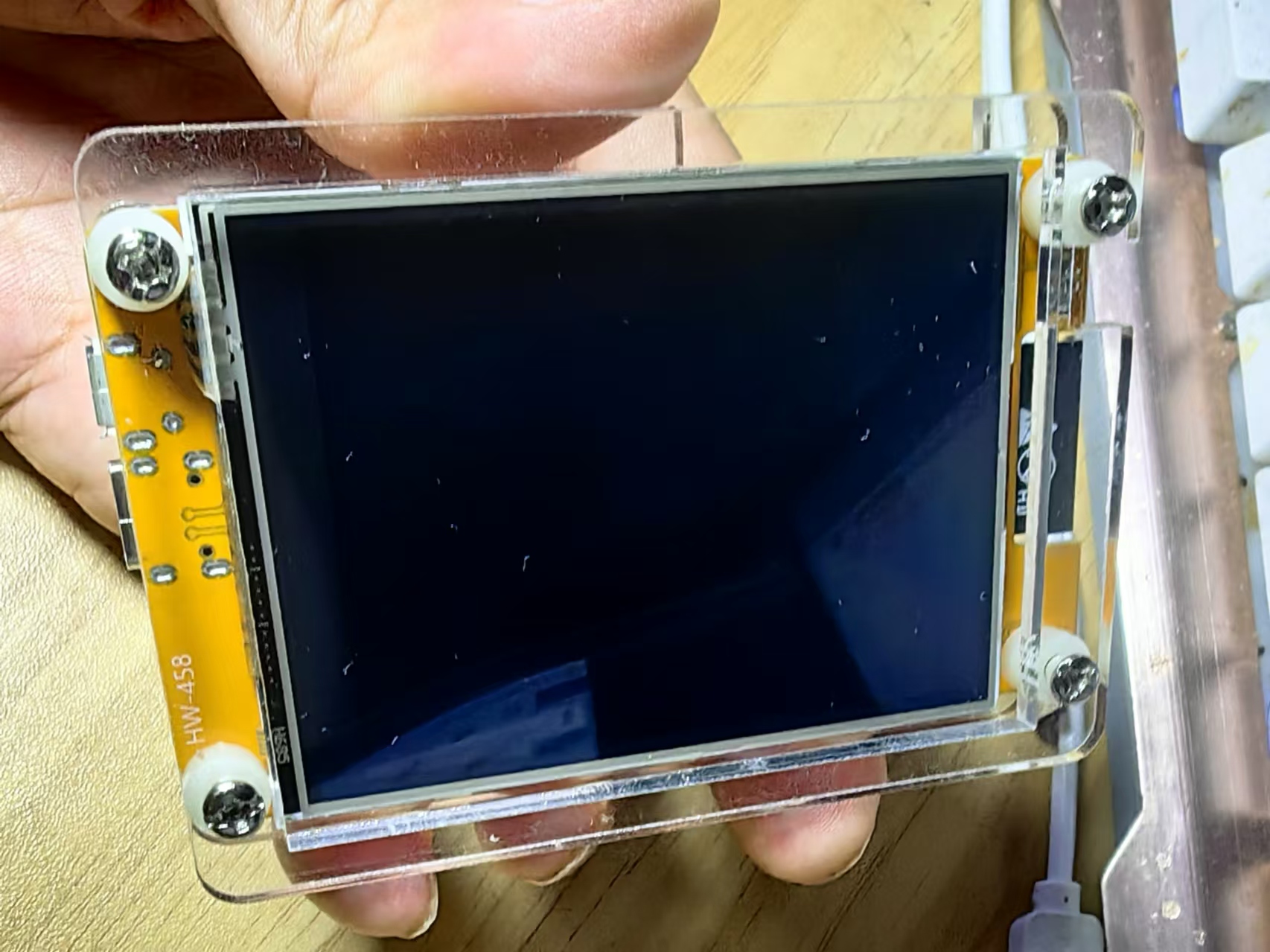
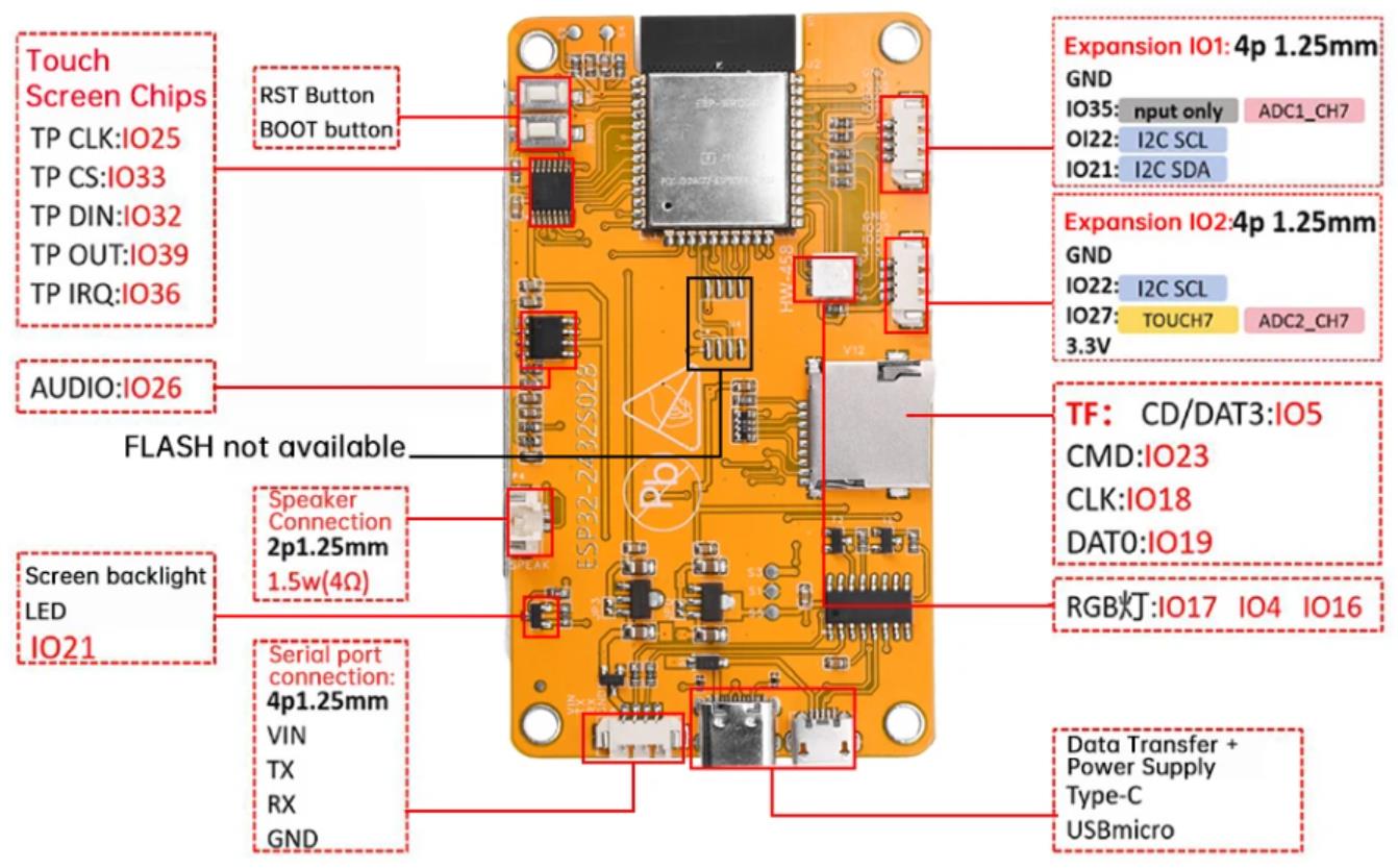
ESP32-CYD(2432S028)液晶2.8寸屏开发板使用ESP32-WROOM-32模块作为主控,主控是一款双核MCU,集成了Wi-Fi和蓝牙功能,主频可达240MHz,具有520KB的SRAM、448KB的ROM,闪存容量为4MB+4MB,显示分辨率为240x320,采用电阻式触控式屏幕。该模块包括LCD显示器、背光控制电路、触控式屏幕控制电路、扬声器驱动电路、光敏电路和RGB LED控制电路。支持TF卡界面、序列界面、温湿度感测器界面(DHT11界面)和保留的IO口界面,该模块支持在Arduino IDE、ESP IDE、MicroPython和Mixly中进行开发。
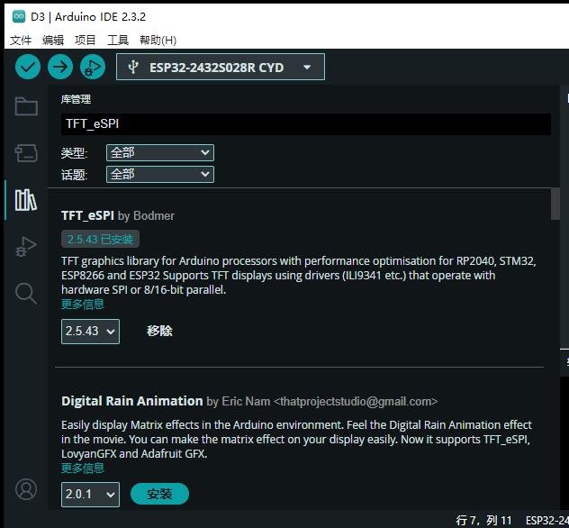
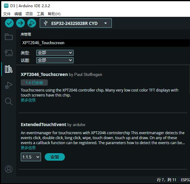
安装TFT_eSPI、XPT2046_Touchscreen、BasicLinearAlgebra和LVGL库
网址:
TFT_eSPI库的网址:https://github.com/Bodmer/TFT_eSPI
XPT2046_Touchscreen库的网址: https://github.com/PaulStoffregen/XPT2046_Touchscreen
BasicLinearAlgebra库:https://github.com/tomstewart89/BasicLinearAlgebra
要正确使用 TFT_eSPI 库,需要根据不同开发板与TFT屏幕正确配置User_Setup.h和lv_conf.h文件。
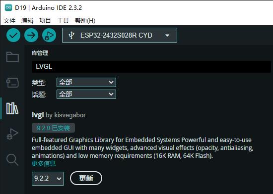
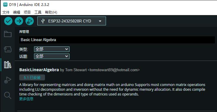
大多数情况下,默认情况下,您的触摸屏可能没有精确校准,这是正常的。
通常,x 轴和 y 轴只偏离几个像素,例如,当使用较大的小部件(例如大按钮)时,这不会很明显。但是,当需要更高的精度时,例如使用具有较小键的键盘时,校准是一个关键方面。
校准方法
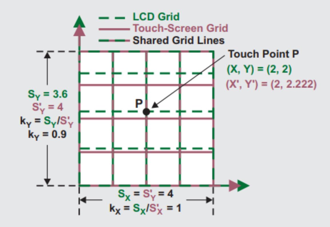
校准触摸屏涉及确定六个不同系数的值,然后将这些系数用于校准方程式中,以确定 (x,y) 坐标的实际值。
【Arduino】168种传感器模块系列实验(资料代码+仿真编程+图形编程)
实验二百三十八:ESP32开发板WiFi蓝牙2.8寸240*320智能液晶显示屏带触摸屏TFT模块
项目实验之二十:ESP32 CYD液晶2.8寸开发板电阻式触摸屏校准
实验开源代码
/*
  【Arduino】168种传感器模块系列实验(资料代码+仿真编程+图形编程)
  实验二百三十八:ESP32开发板WiFi蓝牙2.8寸240*320智能液晶显示屏带触摸屏TFT模块
  项目实验之二十:ESP32 CYD液晶2.8寸开发板电阻式触摸屏校准
*/

#include <lvgl.h>                 // 引入LVGL图形库
#include <TFT_eSPI.h>             // 引入TFT_eSPI库,用于驱动TFT显示屏
#include <XPT2046_Touchscreen.h>  // 引入XPT2046触摸屏库
#include <BasicLinearAlgebra.h>   // 引入线性代数库,用于计算触摸屏校准参数

// Touchscreen pins
#define XPT2046_IRQ 36   // T_IRQ
#define XPT2046_MOSI 32  // T_DIN
#define XPT2046_MISO 39  // T_OUT
#define XPT2046_CLK 25   // T_CLK
#define XPT2046_CS 33    // T_CS

unsigned long delay_start = 0;
#define DELAY_1S 1000
#define DELAY_5S 5000

SPIClass touchscreenSPI = SPIClass(VSPI);
XPT2046_Touchscreen touchscreen(XPT2046_CS, XPT2046_IRQ);

#define SCREEN_WIDTH 240
#define SCREEN_HEIGHT 320

String s;

int ts_points[6][2];

/* define the screen points where touch samples will be taken */
const int scr_points[6][2] = { {13, 11}, {20, 220}, {167, 60}, {155, 180}, {300, 13}, {295, 225} };

struct point {
  int x;
  int y;
};

/* pS is a screen point; pT is a resistive touchscreen point */
struct point aS = {scr_points[0][0], scr_points[0][1] };
struct point bS = {scr_points[1][0], scr_points[1][1] };
struct point cS = {scr_points[2][0], scr_points[2][1] };
struct point dS = {scr_points[3][0], scr_points[3][1] };
struct point eS = {scr_points[4][0], scr_points[4][1] };
struct point fS = {scr_points[5][0], scr_points[5][1] };

struct point aT;
struct point bT;
struct point cT;
struct point dT;
struct point eT;
struct point fT;

/* coefficients for transforming the X and Y coordinates of the resistive touchscreen
   to display coordinates... the ones with the "pref_" prefix are retrieved from NVS   */
float alphaX, betaX, deltaX, alphaY, betaY, deltaY;
float pref_alphaX, pref_betaX, pref_deltaX, pref_alphaY, pref_betaY, pref_deltaY;

#define DRAW_BUF_SIZE (SCREEN_WIDTH * SCREEN_HEIGHT / 10 * (LV_COLOR_DEPTH / 8))
uint32_t draw_buf[DRAW_BUF_SIZE / 4];

// If logging is enabled, it will inform the user about what is happening in the library
void log_print(lv_log_level_t level, const char * buf) {
  LV_UNUSED(level);
  Serial.println(buf);
  Serial.flush();
}

// Declare function to get the Raw Touchscreen data
void touchscreen_read_pts(bool, bool, int, int);

/* Declare function to display a user instruction upon startup */
void lv_display_instruction(void);

/* Declare function to display crosshair at indexed point */
void display_crosshair(int);

/* Declare function to display crosshairs at given coordinates */
void display_crosshairs(int, int);

/* Declare function to display 'X's at given coordinates */
void display_xs(int, int);

/* Declare function to compute the resistive touchscreen coordinates to display coordinates conversion coefficients */
void ts_calibration (
  const point, const point,
	const point, const point,
	const point, const point,
  const point, const point,
	const point, const point,
	const point, const point);

void gather_cal_data(void) {
  //Function to draw the crosshairs and collect data
  bool reset, finished;
  int x_avg, y_avg;

  for (int i = 0; i < 6; i++) {
    lv_obj_clean(lv_scr_act());
    //lv_draw_cross(i);
    display_crosshair(i);

    reset = true;
    x_avg = 0;
    y_avg = 0;

    touchscreen_read_pts(reset, &finished, &x_avg, &y_avg);

    reset = false;
    while (!finished) {
      touchscreen_read_pts(reset, &finished, &x_avg, &y_avg);

      /* found out the hard way that if I don't do this, the screen doesn't update */
      lv_task_handler();
      lv_tick_inc(10);
      delay(10);
    }

    lv_obj_clean(lv_scr_act());
    lv_task_handler();
    lv_tick_inc(10);
    delay(10);

    ts_points[i][0] = x_avg;
    ts_points[i][1] = y_avg;

    String s = String("x_avg = " + String(x_avg) + " y_avg = " + String(y_avg) );
    Serial.println(s);
    delay(1500);
  }
}

void compute_transformation_coefficients(void) {
  /* finished collecting data, now compute correction coefficients */
  /* first initialize the function call parameters */
  aT = { ts_points[0][0], ts_points[0][1] };
  bT = { ts_points[1][0], ts_points[1][1] };
  cT = { ts_points[2][0], ts_points[2][1] };
  dT = { ts_points[3][0], ts_points[3][1] };
  eT = { ts_points[4][0], ts_points[4][1] };
  fT = { ts_points[5][0], ts_points[5][1] };

  /* compute the resisitve touchscreen to display coordinates conversion coefficients */
  ts_calibration(aS, aT, bS, bT, cS, cT, dS, dT, eS, eT, fS, fT);
}

void check_calibration_results(void) {
  int x_touch, y_touch, x_scr, y_scr, error;

  /* if we did our job well, the screen points computed below should match
     aS, bS, and cS defined near the top */
  for (int i = 0; i < 6; i++) {
    /* define some touch points and translate them to screen points */
    x_touch = ts_points[i][0];
    y_touch = ts_points[i][1];

    /* here's the magic equation that uses the magic coefficients */
    /* use it to convert resistive touchscreen points to display points */
    x_scr = alphaX * x_touch + betaX * y_touch + deltaX;
    y_scr = alphaY * x_touch + betaY * y_touch + deltaY;

    display_crosshairs(scr_points[i][0], scr_points[i][1]);
    display_xs(x_scr, y_scr);

    s = String("x_touch = " + String(x_touch) + " y_touch = " + String(y_touch) );
    Serial.println(s);

    s = String("x_scr = " + String(x_scr) + " y_scr = " + String(y_scr) );
    Serial.println(s);

    error = (int) sqrt( sq(x_scr - scr_points[i][0]) + sq(y_scr - scr_points[i][1]) );
    s = String("error = " + String(error) );
    Serial.println(s);
    Serial.println();
  }

  Serial.println("******************************************************************");
  Serial.println("******************************************************************");
  Serial.println("USE THE FOLLOWING COEFFICIENT VALUES TO CALIBRATE YOUR TOUCHSCREEN");
  s = String("Computed X:  alpha_x = " + String(alphaX, 3) + ", beta_x = " + String(betaX, 3) + ", delta_x = " + String(deltaX, 3) );
  Serial.println(s);
  s = String("Computed Y:  alpha_y = " + String(-alphaY, 3) + ", beta_y = " + String(-betaY, 3) + ", delta_y = " + String(SCREEN_WIDTH-deltaY, 3) );
  Serial.println(s);
  Serial.println("******************************************************************");
  Serial.println("******************************************************************");
}

void setup() {
  String LVGL_Arduino = String("LVGL Library Version: ") + lv_version_major() + "." + lv_version_minor() + "." + lv_version_patch();
  Serial.begin(115200);
  Serial.println(LVGL_Arduino);

  // Start LVGL
  lv_init();
  // Register print function for debugging
  lv_log_register_print_cb(log_print);

  // Start the SPI for the touchscreen and init the touchscreen
  touchscreenSPI.begin(XPT2046_CLK, XPT2046_MISO, XPT2046_MOSI, XPT2046_CS);
  touchscreen.begin(touchscreenSPI);
  // Set the Touchscreen rotation in landscape mode
  // Note: in some displays, the touchscreen might be upside down, so you might need to set the rotation to 0: touchscreen.setRotation(0);
  touchscreen.setRotation(2);

  // Create a display object
  lv_display_t * disp;
  // Initialize the TFT display using the TFT_eSPI library
  disp = lv_tft_espi_create(SCREEN_WIDTH, SCREEN_HEIGHT, draw_buf, sizeof(draw_buf));
  lv_display_set_rotation(disp, LV_DISPLAY_ROTATION_270);

  lv_display_instruction();
  delay_start = millis();
  while ((millis() - delay_start) < DELAY_5S) {
    lv_task_handler();
    lv_tick_inc(10);
    delay(10);
  }

  /* display crosshairs and have the user tap on them until enough samples are gathered */;
  gather_cal_data();

  /* crunch the numbers to compute the touchscreen to display coordinate transformation equation coefficients */
  compute_transformation_coefficients();

  /* display stored correction data and display generated vs measured screen points */
  check_calibration_results();
}

void loop() {
  lv_task_handler();  // let the GUI do its work
  lv_tick_inc(5);     // tell LVGL how much time has passed
  delay(5);           // let this time pass
}

/* Function to read a number of points from the resistive touchscreen as the user taps
   a stylus on displayed crosshairs.  Once the samples have been collected, they are
   filtered to remove outliers and then averaged and the average x & y are returned to the caller. */
void touchscreen_read_pts(bool reset, bool *finished, int *x_avg, int *y_avg) {
  /* nr_samples = samples taken; good_samples = samples used, samples = array of 100 samples */
  static int i, nr_samples, good_samples;
  static uint32_t samples[100][2];

  /* coordinates to shift and rotate touch screen coordinates to display coordinates */
  static float mean_x, mean_y, filt_mean_x, filt_mean_y, stdev_x, stdev_y;

  /* caller resets the sample run at each new displayed crosshair */
  if (reset) {
    nr_samples = 0;
    *x_avg = 0;
    *y_avg = 0;
    *finished = false;
  }
  // Checks if Touchscreen was touched, and prints X, Y
  if(touchscreen.tirqTouched() && touchscreen.touched()) {
    // Get Touchscreen points
    TS_Point p = touchscreen.getPoint();
    samples[nr_samples][0] = p.x;
    samples[nr_samples][1] = p.y;

    s = String("x, y = " + String(samples[nr_samples][0]) + ", " + String(samples[nr_samples][1]) );
    Serial.println(s);

    nr_samples++;

    /* first compute the x & y averages of all the samples */
    if (nr_samples >= 100) {
      mean_x = 0;
      mean_y = 0;
      for (i = 0; i < 100; i++) {
        mean_x += (float)samples[i][0];
        mean_y += (float)samples[i][1];
      }
      mean_x = mean_x / (float)nr_samples;
      mean_y = mean_y / (float)nr_samples;
      s = String("Unfiltered values:  mean_x = " + String(mean_x) + ", mean_y = " + String(mean_y));
      Serial.println(s);

      /* now compute the x & y standard deviations of all the samples */
      stdev_x = 0;
      stdev_y = 0;
      for (i = 0; i < 100; i++) {
        stdev_x += sq((float)samples[i][0] - mean_x);
        stdev_y += sq((float)samples[i][1] - mean_y);
      }
      stdev_x = sqrt(stdev_x / (float)nr_samples);
      stdev_y = sqrt(stdev_y / (float)nr_samples);

      s = String("stdev_x = " + String(stdev_x) + ", stdev_y = " + String(stdev_y));
      Serial.println(s);

      /* now average the samples that are less than one standard deviation from the mean */
      /* this filtering is called "outlier rejection," and is included because outliers were observed in testing */
      good_samples = 0;
      filt_mean_x = 0;
      filt_mean_y = 0;
      for (i = 0; i < 100; i++) {
        if ((abs((float)samples[i][0] - mean_x) < stdev_x) && (abs((float)samples[i][1] - mean_y) < stdev_y)) {
          filt_mean_x += (float)samples[i][0];
          filt_mean_y += (float)samples[i][1];
          good_samples++;
        }
      }

      s = String("Good samples = " + String(good_samples));
      Serial.println(s);

      filt_mean_x = filt_mean_x / (float)good_samples;
      filt_mean_y = filt_mean_y / (float)good_samples;
      s = String("Filtered values:  filt_mean_x = " + String(filt_mean_x) + ", filt_mean_y = " + String(filt_mean_y));
      Serial.println(s);
      Serial.println();

      *x_avg = (int)mean_x;
      *y_avg = (int)mean_y;

      *finished = true;
    }
  }
  else {
    // nada
  }
}

/* Function to display a user instruction on startup */
void lv_display_instruction(void) {
  // Create a text label aligned center: https://docs.lvgl.io/master/widgets/label.html
  lv_obj_t * text_label = lv_label_create(lv_screen_active());
  lv_label_set_text(text_label, "Tap each crosshair until it disappears.");
  lv_obj_align(text_label, LV_ALIGN_CENTER, 0, 0);
  // Set font type and font size. More information: https://docs.lvgl.io/master/overview/font.html
  static lv_style_t style_text_label;
  lv_style_init(&style_text_label);
  lv_style_set_text_font(&style_text_label, &lv_font_montserrat_14);
  lv_obj_add_style(text_label, &style_text_label, 0);
}

/* function to display crosshair at given index of coordinates array */
void display_crosshair(int cross_nr) {

  static lv_point_precise_t h_line_points[] = { {0, 0}, {10, 0} };
  static lv_point_precise_t v_line_points[] = { {0, 0}, {0, 10} };

  static lv_style_t style_line;
  lv_style_init(&style_line);
  lv_style_set_line_width(&style_line, 2);
  lv_style_set_line_color(&style_line, lv_palette_main(LV_PALETTE_RED));
  lv_style_set_line_rounded(&style_line, true);

  // Create crosshair lines
  lv_obj_t* crosshair_h = lv_line_create(lv_screen_active());
  lv_obj_t* crosshair_v = lv_line_create(lv_screen_active());

  lv_line_set_points(crosshair_h, h_line_points, 2); // Set the coordinates for the crosshair_h line
  lv_obj_add_style(crosshair_h, &style_line, 0);

  lv_line_set_points(crosshair_v, v_line_points, 2); // Set the coordinates for the crosshair_h line
  lv_obj_add_style(crosshair_v, &style_line, 0);

  lv_obj_set_pos(crosshair_h, scr_points[cross_nr][0] - 5, scr_points[cross_nr][1]);
  lv_obj_set_pos(crosshair_v, scr_points[cross_nr][0], scr_points[cross_nr][1] - 5);
}

/* function to display crosshairs at given coordinates */
void display_crosshairs(int x, int y) {

  static lv_point_precise_t h_line_points[] = { {0, 0}, {10, 0} };
  static lv_point_precise_t v_line_points[] = { {0, 0}, {0, 10} };

  static lv_style_t style_line;
  lv_style_init(&style_line);
  lv_style_set_line_width(&style_line, 2);
  lv_style_set_line_color(&style_line, lv_palette_main(LV_PALETTE_BLUE));
  lv_style_set_line_rounded(&style_line, true);

  // Create crosshair lines
  lv_obj_t* crosshair_h = lv_line_create(lv_screen_active());
  lv_obj_t* crosshair_v = lv_line_create(lv_screen_active());

  lv_line_set_points(crosshair_h, h_line_points, 2); // Set the coordinates for the crosshair_h line
  lv_obj_add_style(crosshair_h, &style_line, 0);

  lv_line_set_points(crosshair_v, v_line_points, 2); // Set the coordinates for the crosshair_h line
  lv_obj_add_style(crosshair_v, &style_line, 0);

  lv_obj_set_pos(crosshair_h, x - 5, y);
  lv_obj_set_pos(crosshair_v, x, y - 5);
}

/* function to display 'X's at given coordinates */
void display_xs(int x, int y) {

  static lv_point_precise_t u_line_points[] = { {0, 0}, {10, 10} };  //upsloping
  static lv_point_precise_t d_line_points[] = { {0, 10}, {10, 0} };  //downsloping

  static lv_style_t style_line;
  lv_style_init(&style_line);
  lv_style_set_line_width(&style_line, 2);
  lv_style_set_line_color(&style_line, lv_palette_main(LV_PALETTE_RED));
  lv_style_set_line_rounded(&style_line, true);

  // Create crosshair lines
  lv_obj_t* x_u = lv_line_create(lv_screen_active());
  lv_obj_t* x_d = lv_line_create(lv_screen_active());

  lv_line_set_points(x_u, u_line_points, 2); // Set the coordinates for the upsloping line
  lv_obj_add_style(x_u, &style_line, 0);

  lv_line_set_points(x_d, d_line_points, 2); // Set the coordinates for the downsloping line
  lv_obj_add_style(x_d, &style_line, 0);

  lv_obj_set_pos(x_u, x - 5, y - 5);
  lv_obj_set_pos(x_d, x - 5, y - 5);
}

/* function to compute the transformation equation coefficients from resistive touchscreen
   coordinates to display coordinates...
  This was based on the Texas Instruments appnote at:
  https://www.ti.com/lit/an/slyt277/slyt277.pdf
  It implements Equation 7 of that appnote, which computes a least-squares set of coefficients. */
void ts_calibration (
	const point aS, const point aT,
	const point bS, const point bT,
	const point cS, const point cT,
  const point dS, const point dT,
	const point eS, const point eT,
	const point fS, const point fT) {

	bool defined;
	uint16_t screenWidth, screenHeight;

  BLA::Matrix<6, 3> A;
  BLA::Matrix<3, 6> transA;
  BLA::Matrix<6> X;
  BLA::Matrix<6> Y;
  BLA::Matrix<3, 3> B;
  BLA::Matrix<3, 6> C;
  BLA::Matrix<3> X_coeff;
  BLA::Matrix<3> Y_coeff;

  s = String("aS = " + String(aS.x) + ", " + String(aS.y));
  Serial.println(s);
  s = String("bS = " + String(bS.x) + ", " + String(bS.y));
  Serial.println(s);
  s = String("cS = " + String(cS.x) + ", " + String(cS.y));
  Serial.println(s);
  s = String("dS = " + String(dS.x) + ", " + String(dS.y));
  Serial.println(s);
  s = String("eS = " + String(eS.x) + ", " + String(eS.y));
  Serial.println(s);
  s = String("fS = " + String(fS.x) + ", " + String(fS.y));
  Serial.println(s);

  s = String("aT = " + String(aT.x) + ", " + String(aT.y));
  Serial.println(s);
  s = String("bT = " + String(bT.x) + ", " + String(bT.y));
  Serial.println(s);
  s = String("cT = " + String(cT.x) + ", " + String(cT.y));
  Serial.println(s);
  s = String("eT = " + String(dT.x) + ", " + String(dT.y));
  Serial.println(s);
  s = String("eT = " + String(eT.x) + ", " + String(eT.y));
  Serial.println(s);
  s = String("fT = " + String(fT.x) + ", " + String(fT.y));
  Serial.println(s);
  Serial.println();

  struct f_point {
    float x;
    float y;
  };

  struct f_point faS, fbS, fcS, fdS, feS, ffS, faT, fbT, fcT, fdT, feT, ffT;

  faS.x = (float)aS.x; fbS.x = (float)bS.x; fcS.x = (float)cS.x, fdS.x = (float)dS.x; feS.x = (float)eS.x; ffS.x = (float)fS.x;
  faS.y = (float)aS.y; fbS.y = (float)bS.y; fcS.y = (float)cS.y; fdS.y = (float)dS.y; feS.y = (float)eS.y; ffS.y = (float)fS.y;

  faT.x = (float)aT.x; fbT.x = (float)bT.x; fcT.x = (float)cT.x; fdT.x = (float)dT.x; feT.x = (float)eT.x; ffT.x = (float)fT.x;
  faT.y = (float)aT.y; fbT.y = (float)bT.y; fcT.y = (float)cT.y; fdT.y = (float)dT.y; feT.y = (float)eT.y; ffT.y = (float)fT.y;

  A = { faT.x, faT.y, 1,
        fbT.x, fbT.y, 1,
        fcT.x, fcT.y, 1,
        fdT.x, fdT.y, 1,
        feT.x, feT.y, 1,
        ffT.x, ffT.y, 1 };

  X = { faS.x,
        fbS.x,
        fcS.x,
        fdS.x,
        feS.x,
        ffS.x };

  Y = { faS.y,
        fbS.y,
        fcS.y,
        fdS.y,
        feS.y,
        ffS.y };

  /* Now compute [AtA]^-1 * AtA * X and [AtA]^-1 * AtA * Y */
  Serial.print ("A = ");
  Serial.println(A);

  transA = ~A;
  Serial.print ("transA = ");
  Serial.println(transA);

  B = transA * A;
  Serial.print ("Before inversion, B = ");
  Serial.println(B);

  if (!Invert(B) ) {
    Serial.println("Singular matrix in computation of inverse of B = transA*A!");
  }
  Serial.print ("After inversion, B = ");
  Serial.println(B);

  C = B * transA;
  Serial.print ("C = ");
  Serial.println(C);

  X_coeff = C * X;
  Y_coeff = C * Y;

  /* transfer the X and Y coefficients to the Greek-letter variables
     Note that BLA requires round brackets while MatrixMath requires square ones */
  alphaX = X_coeff(0); betaX = X_coeff(1); deltaX = X_coeff(2);
  alphaY = Y_coeff(0); betaY = Y_coeff(1); deltaY = Y_coeff(2);

  Serial.println();
}
运行该草图后,您应该使用触控笔(显示屏随附的触控笔)在初始文本显示后一次显示一个的六个“+”号的中心重复并尽可能精确地点击每个符号的中心。
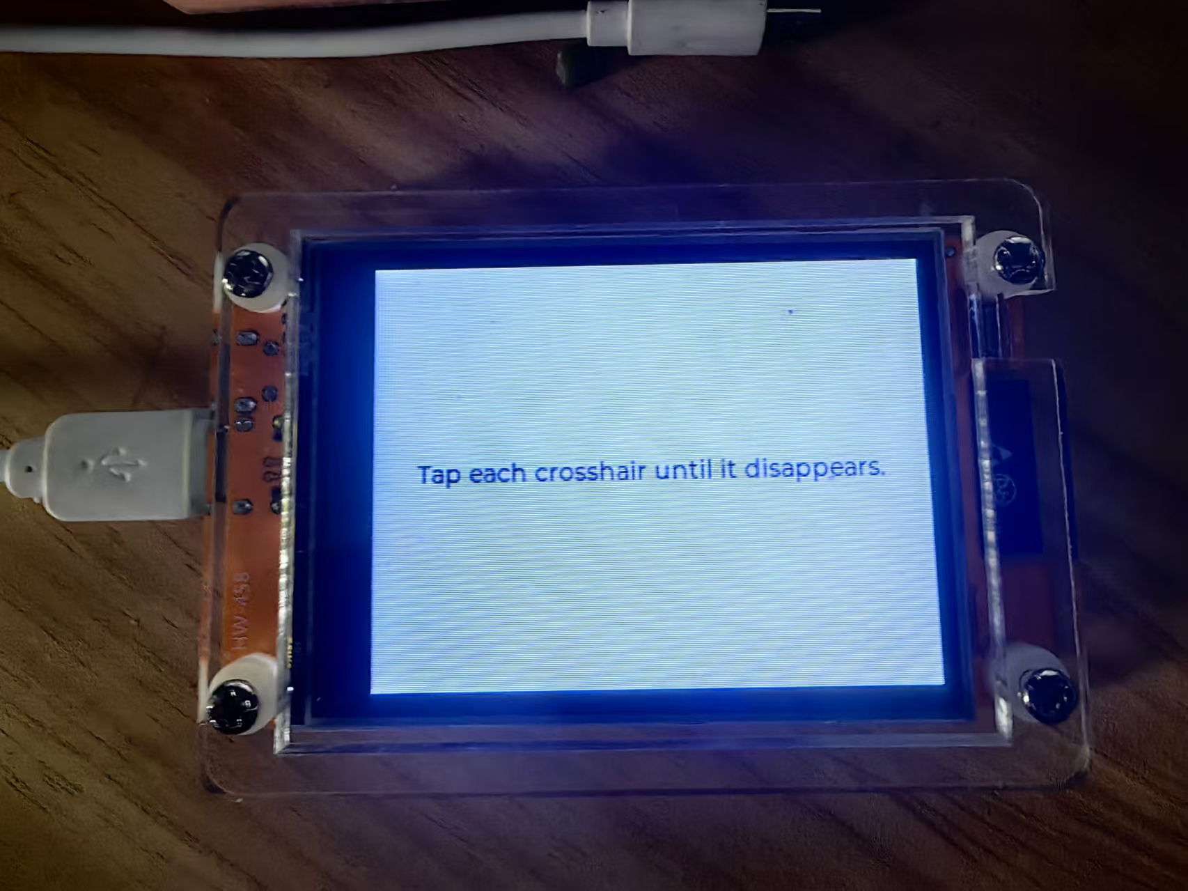
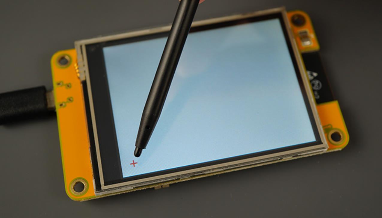
当 “+” 号消失时停止点击,并观察另一个 “+” 号的出现,“+” 号总共出现 6 次。
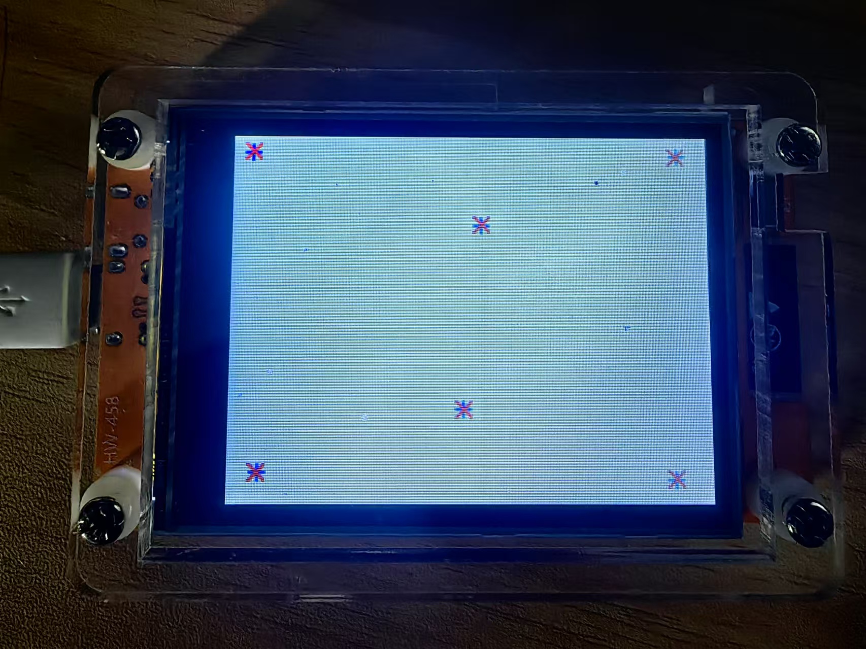
在草图处理完您用点击创建的电阻式触摸屏样本后,在校准程序之后,它将显示六个“+”符号,在它认为您点击的地方显示六个“×”。
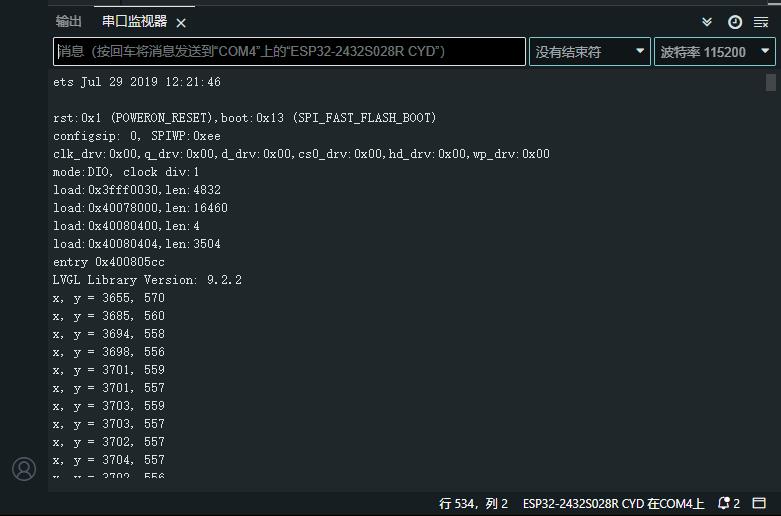
实验串口返回情况
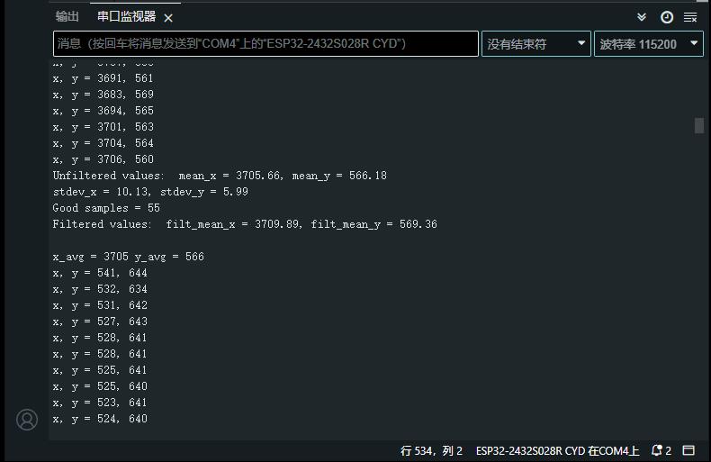
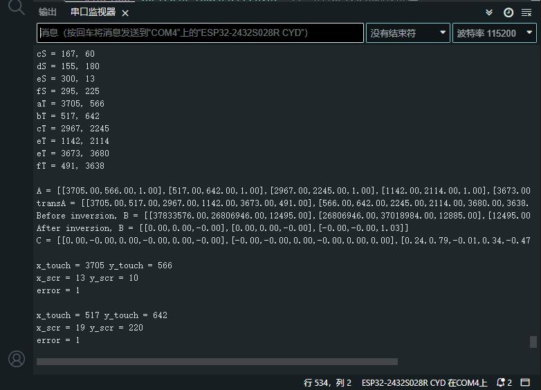
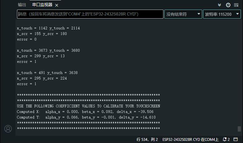
USE THE FOLLOWING COEFFICIENT VALUES TO CALIBRATE YOUR TOUCHSCREEN
Computed X: alpha_x = 0.000, beta_x = 0.092, delta_x = -39.506
Computed Y: alpha_y = 0.066, beta_y = -0.001, delta_y = -14.610
【Arduino】168种传感器模块系列实验(资料代码+仿真编程+图形编程)
实验二百三十八:ESP32开发板WiFi蓝牙2.8寸240*320智能液晶显示屏带触摸屏TFT模块
项目实验之二十一:ESP32 CYD液晶2.8寸开发板电阻式触摸屏使用校准方程来测试触摸屏
(在运行代码之前,请确保修改代码以使用在上一个测试中获得的系数。)
实验开源代码
/*
  【Arduino】168种传感器模块系列实验(资料代码+仿真编程+图形编程)
  实验二百三十八:ESP32开发板WiFi蓝牙2.8寸240*320智能液晶显示屏带触摸屏TFT模块
  项目实验之二十一:ESP32 CYD液晶2.8寸开发板电阻式触摸屏使用校准方程来测试触摸屏
  (在运行代码之前,请确保修改代码以使用在上一个测试中获得的系数。)
*/

#include <lvgl.h>                 // 引入LVGL图形库
#include <TFT_eSPI.h>             // 引入TFT_eSPI库,用于驱动TFT显示屏
#include <XPT2046_Touchscreen.h>  // 引入XPT2046触摸屏库

// Touchscreen pins
#define XPT2046_IRQ 36   // T_IRQ
#define XPT2046_MOSI 32  // T_DIN
#define XPT2046_MISO 39  // T_OUT
#define XPT2046_CLK 25   // T_CLK
#define XPT2046_CS 33    // T_CS

SPIClass touchscreenSPI = SPIClass(VSPI);
XPT2046_Touchscreen touchscreen(XPT2046_CS, XPT2046_IRQ);

#define SCREEN_WIDTH 240
#define SCREEN_HEIGHT 320

// Touchscreen coordinates: (x, y) and pressure (z)
int x, y, z;

#define DRAW_BUF_SIZE (SCREEN_WIDTH * SCREEN_HEIGHT / 10 * (LV_COLOR_DEPTH / 8))
uint32_t draw_buf[DRAW_BUF_SIZE / 4];

// If logging is enabled, it will inform the user about what is happening in the library
void log_print(lv_log_level_t level, const char * buf) {
  LV_UNUSED(level);
  Serial.println(buf);
  Serial.flush();
}

static lv_obj_t * text_label_touch;
// Get the Touchscreen data
void touchscreen_read(lv_indev_t * indev, lv_indev_data_t * data) {
  // Checks if Touchscreen was touched, and prints X, Y and Pressure (Z)
  if(touchscreen.tirqTouched() && touchscreen.touched()) {
    // Get Touchscreen points
    TS_Point p = touchscreen.getPoint();

    // Advanced Touchscreen calibration, LEARN MORE » https://RandomNerdTutorials.com/touchscreen-calibration/
    float alpha_x, beta_x, alpha_y, beta_y, delta_x, delta_y;

    // REPLACE WITH YOUR OWN CALIBRATION VALUES » https://RandomNerdTutorials.com/touchscreen-calibration/
    alpha_x = -0.000;
    beta_x  =  0.092;
    delta_x = -39.506;
    alpha_y =  0.066;
    beta_y =  -0.001;
    delta_y = -14.610;

    x = alpha_y * p.x + beta_y * p.y + delta_y;
    // clamp x between 0 and SCREEN_WIDTH - 1
    x = max(0, x);
    x = min(SCREEN_WIDTH - 1, x);

    y = alpha_x * p.x + beta_x * p.y + delta_x;
    // clamp y between 0 and SCREEN_HEIGHT - 1
    y = max(0, y);
    y = min(SCREEN_HEIGHT - 1, y);

    // Basic Touchscreen calibration points with map function to the correct width and height
    //x = map(p.x, 200, 3700, 1, SCREEN_WIDTH);
    //y = map(p.y, 240, 3800, 1, SCREEN_HEIGHT);

    z = p.z;

    data->state = LV_INDEV_STATE_PRESSED;

    // Set the coordinates
    data->point.x = x;
    data->point.y = y;

    // Print Touchscreen info about X, Y and Pressure (Z) on the Serial Monitor
    Serial.print("X = ");
    Serial.print(x);
    Serial.print(" | Y = ");
    Serial.print(y);
    Serial.print(" | Pressure = ");
    Serial.print(z);
    Serial.println();
    // Print the coordinates on the screen
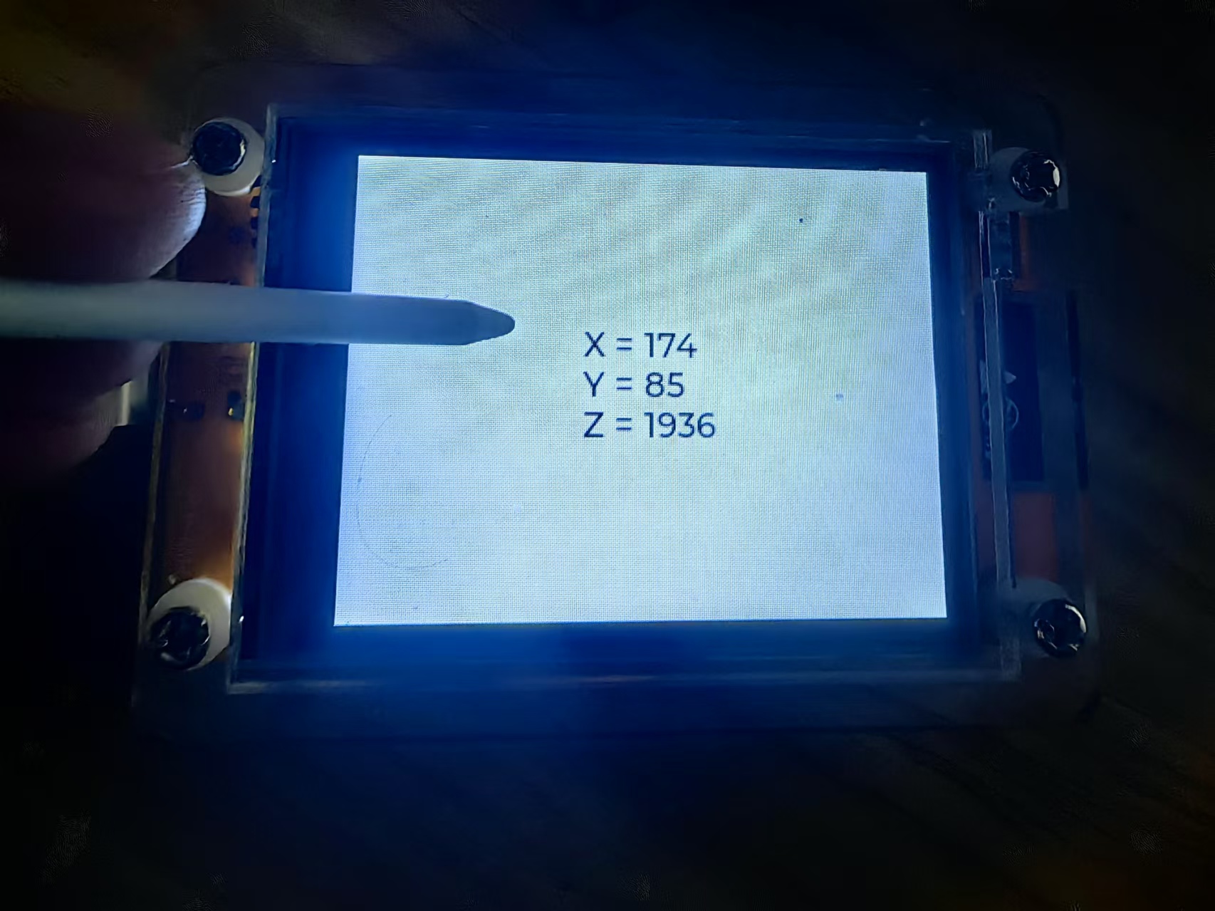
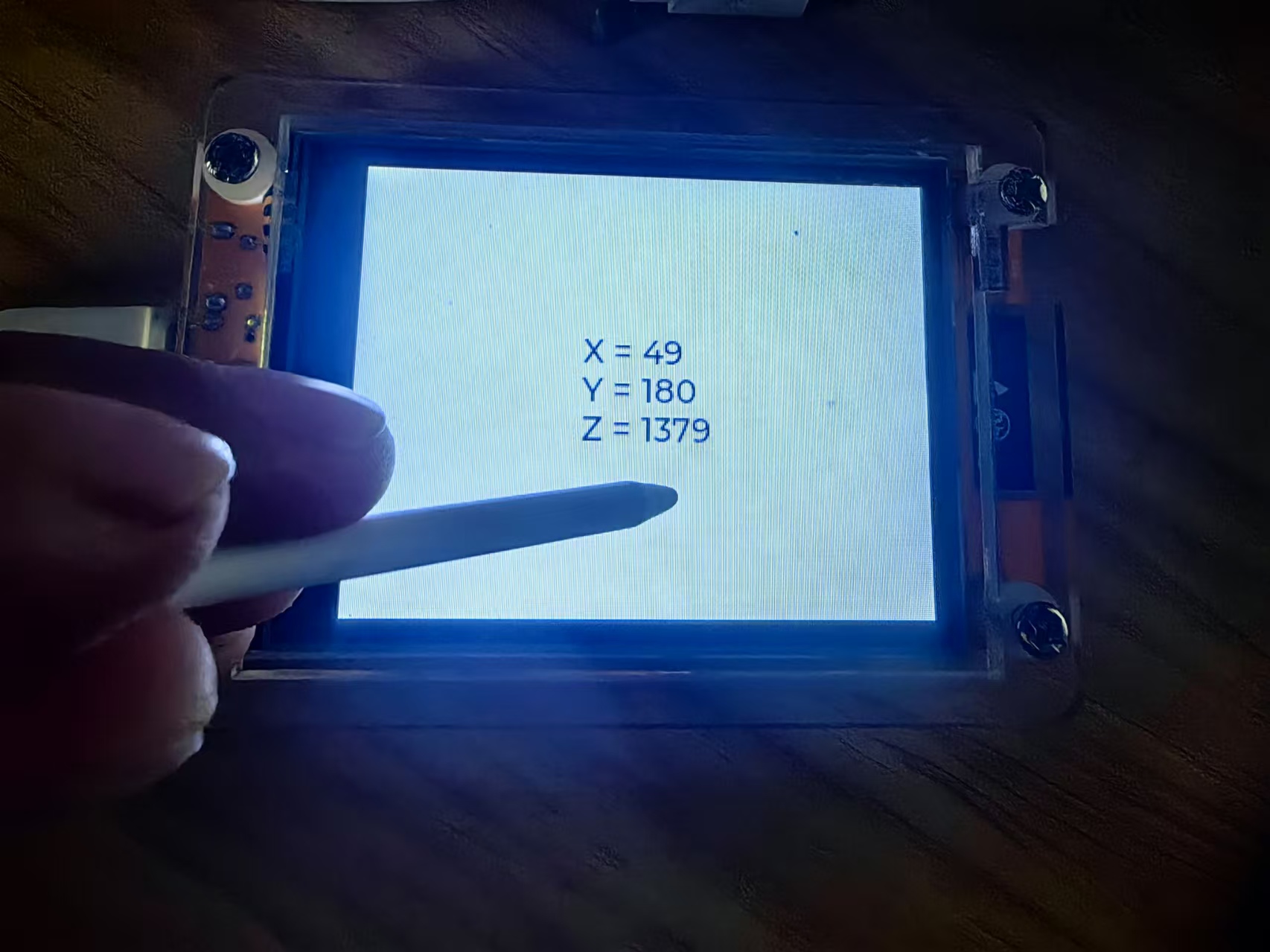
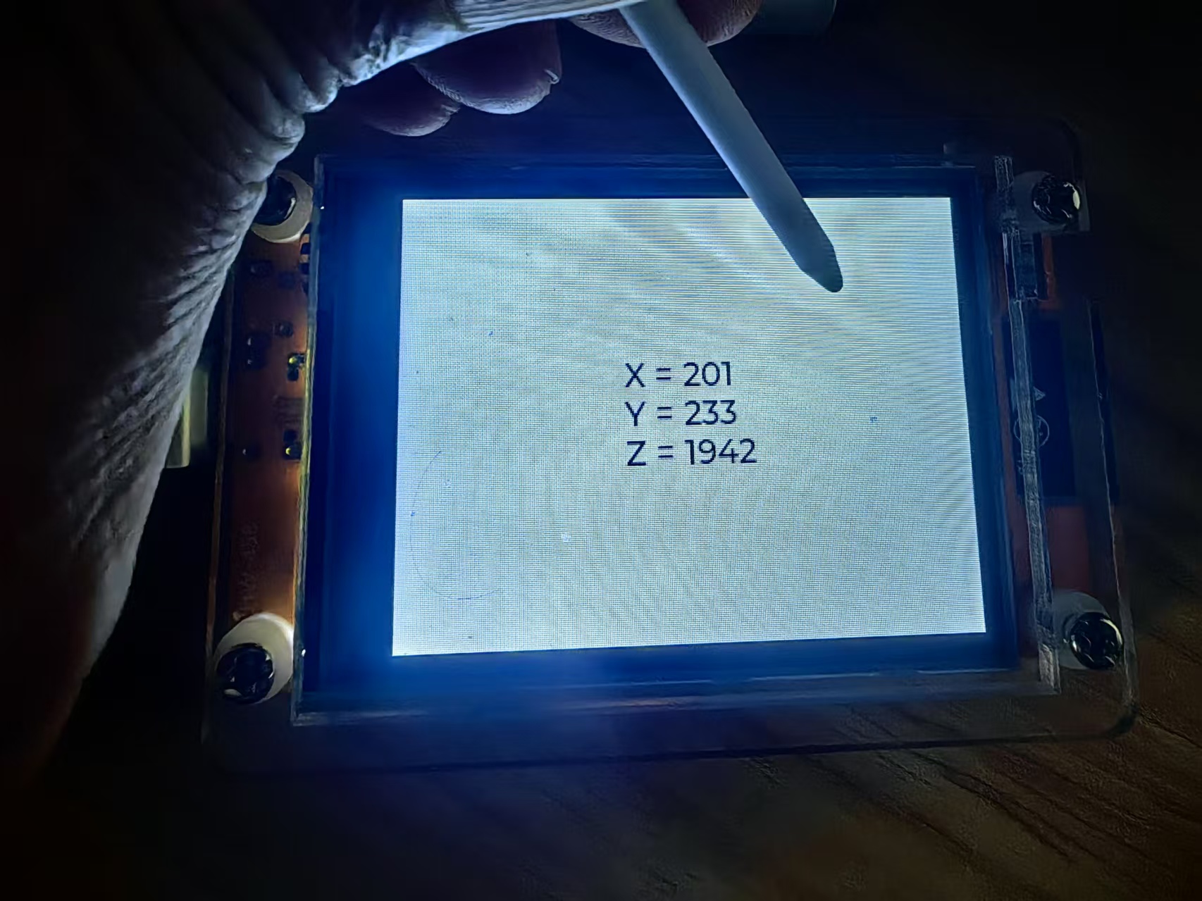
    String touch_data = "X = " + String(x) + "\nY = " + String(y) + "\nZ = " + String(z);
    lv_label_set_text(text_label_touch, touch_data.c_str());
  }
  else {
    data->state = LV_INDEV_STATE_RELEASED;
  }
}


void lv_create_main_gui(void) {
  // Create a text label aligned center: https://docs.lvgl.io/master/widgets/label.html
  text_label_touch = lv_label_create(lv_screen_active());
  lv_label_set_text(text_label_touch, "Touch screen to test");
  lv_obj_align(text_label_touch, LV_ALIGN_CENTER, 0, 0);

  // Set font type and size. More information: https://docs.lvgl.io/master/overview/font.html
  static lv_style_t style_text_label;
  lv_style_init(&style_text_label);
  lv_style_set_text_font(&style_text_label, &lv_font_montserrat_18);
  lv_obj_add_style(text_label_touch, &style_text_label, 0);
}

void setup() {
  String LVGL_Arduino = String("LVGL Library Version: ") + lv_version_major() + "." + lv_version_minor() + "." + lv_version_patch();
  Serial.begin(115200);
  Serial.println(LVGL_Arduino);

  // Start LVGL
  lv_init();
  // Register print function for debugging
  lv_log_register_print_cb(log_print);

  // Start the SPI for the touchscreen and init the touchscreen
  touchscreenSPI.begin(XPT2046_CLK, XPT2046_MISO, XPT2046_MOSI, XPT2046_CS);
  touchscreen.begin(touchscreenSPI);
  // Set the Touchscreen rotation in landscape mode
  // Note: in some displays, the touchscreen might be upside down, so you might need to set the rotation to 0: touchscreen.setRotation(0);
  touchscreen.setRotation(2);

  // Create a display object
  lv_display_t * disp;
  // Initialize the TFT display using the TFT_eSPI library
  disp = lv_tft_espi_create(SCREEN_WIDTH, SCREEN_HEIGHT, draw_buf, sizeof(draw_buf));
  lv_display_set_rotation(disp, LV_DISPLAY_ROTATION_270);

  // Initialize an LVGL input device object (Touchscreen)
  lv_indev_t * indev = lv_indev_create();
  lv_indev_set_type(indev, LV_INDEV_TYPE_POINTER);
  // Set the callback function to read Touchscreen input
  lv_indev_set_read_cb(indev, touchscreen_read);

  // Function to draw the GUI with switches
  lv_create_main_gui();
}

void loop() {
  lv_task_handler();  // let the GUI do its work
  lv_tick_inc(5);     // tell LVGL how much time has passed
  delay(5);           // let this time pass
}
实验串口返回情况
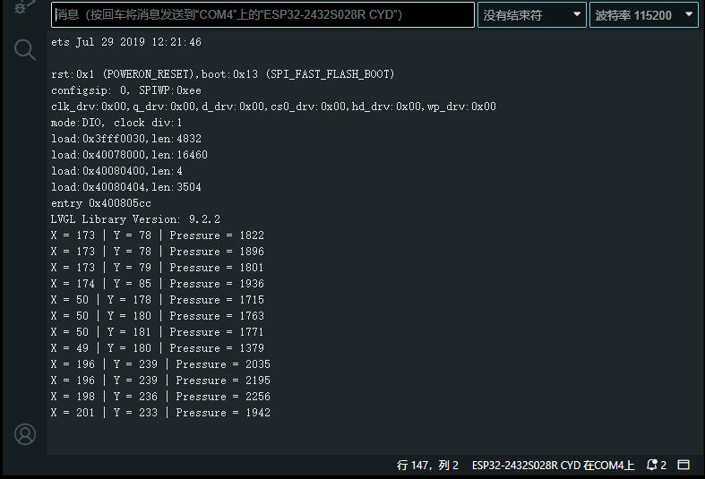
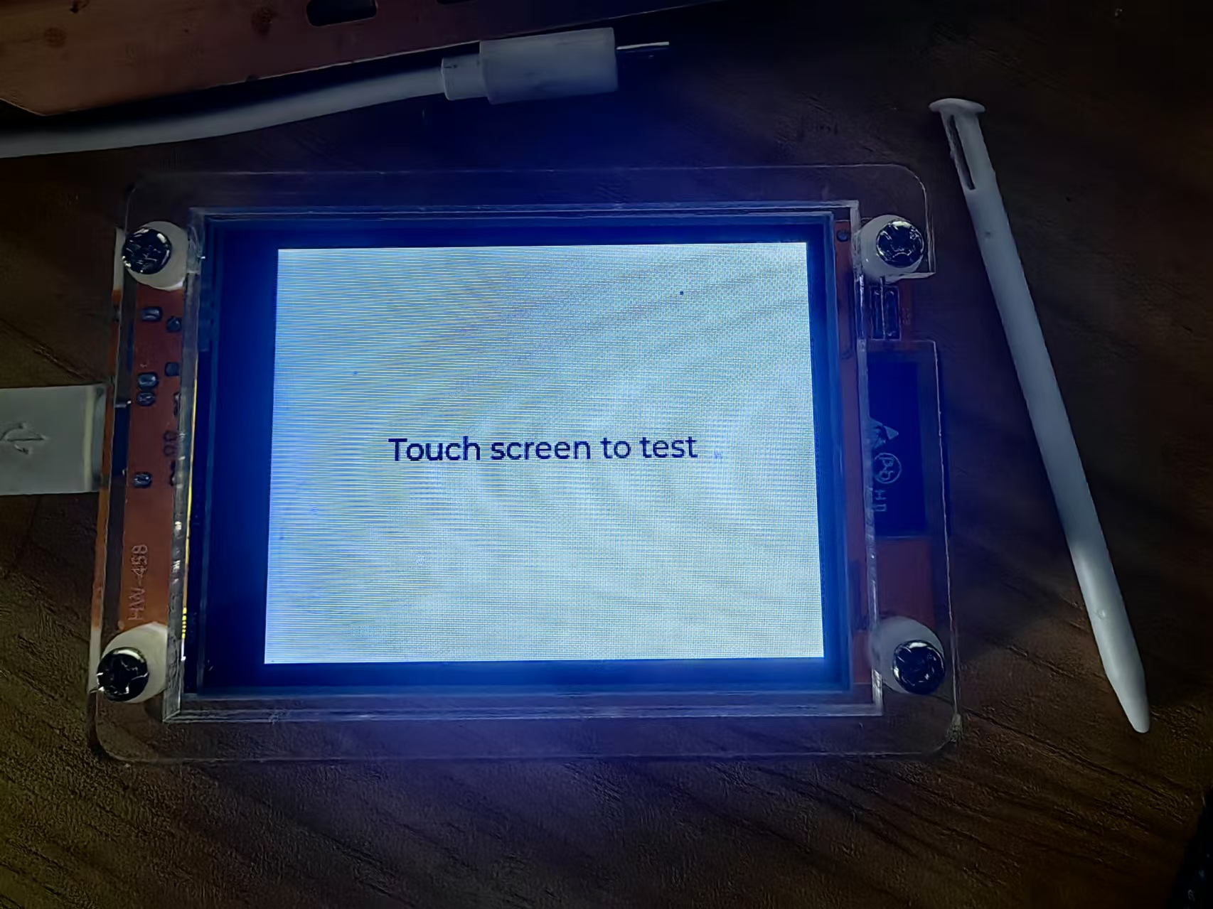
现在,当您触摸屏幕时,您应该会获得校准的 X 和 Y 值。

 返回首页
返回首页
 回到顶部
回到顶部


评论