 返回首页
返回首页
 回到顶部
回到顶部
背景
上一篇使用blinker的时候,就发现视频流不太好用,这里先挖个坑,留着后面我再用esp32-cam来测试一下。
这个方案,我就想使用网页视频传输的方式,结合控件,来看看能不能直接在网页或者手机APP上来控制这个机器人。
功能实现
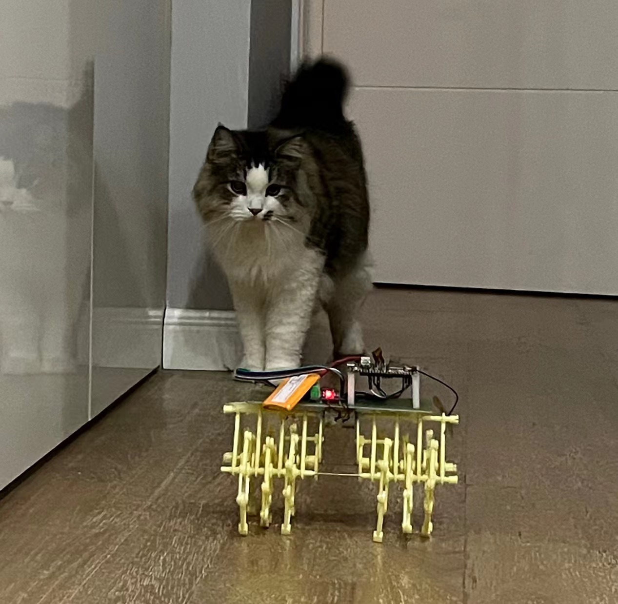
电路连接和材料还是使用的之前的材料,这里的变化就是调整了软件上面的实现方式。
根据样例程序,修改了摄像头的电源控制以及网络连接方式。
代码
#include "esp_camera.h"
#include <WiFi.h>
#include <ArduinoOTA.h>

/* Wifi Crdentials */
String sta_ssid = "******";     // set Wifi network you want to connect to
String sta_password = "******";   // set password for Wifi network

/* define CAMERA_MODEL_AI_THINKER */
#define PWDN_GPIO_NUM     -1
#define RESET_GPIO_NUM    -1
#define XCLK_GPIO_NUM     45
#define SIOD_GPIO_NUM     1
#define SIOC_GPIO_NUM     2

#define Y9_GPIO_NUM       48
#define Y8_GPIO_NUM       46
#define Y7_GPIO_NUM       8
#define Y6_GPIO_NUM       7
#define Y5_GPIO_NUM       4
#define Y4_GPIO_NUM       41
#define Y3_GPIO_NUM       40
#define Y2_GPIO_NUM       39
#define VSYNC_GPIO_NUM    6
#define HREF_GPIO_NUM     42
#define PCLK_GPIO_NUM     5

#include "DFRobot_AXP313A.h"

DFRobot_AXP313A axp;
/* Defining motor and servo pins */
extern int DRV_A = 12;
extern int DRV_B = 13;
extern int DIR_A = 14;
extern int DIR_B = 15;

extern int ledVal = 20;  // setting bright of flash LED 0-255

extern int ledPin = 4;  // set digital pin GPIO4 as LED pin (use biult-in LED)
extern int buzzerPin = 2;  // set digital pin GPIO2 as LED pin (use Active Buzzer)
extern int servoPin = 2;  // set digital pin GPIO2 as servo pin (use SG90)

unsigned long previousMillis = 0;

void startCameraServer();

void initServo() {
  ledcSetup(8, 50, 16); /*50 hz PWM, 16-bit resolution and range from 3250 to 6500 */
  ledcAttachPin(servoPin, 8);
}

void initLed() {
  ledcSetup(7, 5000, 8); /* 5000 hz PWM, 8-bit resolution and range from 0 to 255 */
  ledcAttachPin(ledPin, 7);
}

void setup() {
  Serial.begin(115200);         // set up seriamonitor at 115200 bps
  Serial.setDebugOutput(true);
  Serial.println();
  while(axp.begin() != 0){
    Serial.println("init error");
    delay(1000);
  }
  axp.enableCameraPower(axp.eOV2640);//设置摄像头供电
  Serial.println("*ESP32 Camera Remote Control - L293D Bluino Shield*");
  Serial.println("--------------------------------------------------------");

  // Set all the motor control pin to Output
  pinMode(DRV_A, OUTPUT);
  pinMode(DRV_B, OUTPUT);
  pinMode(DIR_A, OUTPUT);
  pinMode(DIR_B, OUTPUT);

  pinMode(ledPin, OUTPUT); // set the LED pin as an Output
  pinMode(buzzerPin, OUTPUT); // set the buzzer pin as an Output
  pinMode(servoPin, OUTPUT); // set the servo pin as an Output

  // Initial state - turn off motors, LED & buzzer
  digitalWrite(DRV_A, LOW);
  digitalWrite(DRV_B, LOW);
  digitalWrite(DIR_A, LOW);
  digitalWrite(DIR_B, LOW);
  digitalWrite(ledPin, LOW);
  digitalWrite(buzzerPin, LOW);
  digitalWrite(servoPin, LOW);

  /* Initializing Servo and LED */
  initServo();
  initLed();

  camera_config_t config;
  config.ledc_channel = LEDC_CHANNEL_0;
  config.ledc_timer = LEDC_TIMER_0;
  config.pin_d0 = Y2_GPIO_NUM;
  config.pin_d1 = Y3_GPIO_NUM;
  config.pin_d2 = Y4_GPIO_NUM;
  config.pin_d3 = Y5_GPIO_NUM;
  config.pin_d4 = Y6_GPIO_NUM;
  config.pin_d5 = Y7_GPIO_NUM;
  config.pin_d6 = Y8_GPIO_NUM;
  config.pin_d7 = Y9_GPIO_NUM;
  config.pin_xclk = XCLK_GPIO_NUM;
  config.pin_pclk = PCLK_GPIO_NUM;
  config.pin_vsync = VSYNC_GPIO_NUM;
  config.pin_href = HREF_GPIO_NUM;
  config.pin_sscb_sda = SIOD_GPIO_NUM;
  config.pin_sscb_scl = SIOC_GPIO_NUM;
  config.pin_pwdn = PWDN_GPIO_NUM;
  config.pin_reset = RESET_GPIO_NUM;
  config.xclk_freq_hz = 20000000;
  config.pixel_format = PIXFORMAT_JPEG;
  //init with high specs to pre-allocate larger buffers
  if(psramFound()){
    config.frame_size = FRAMESIZE_UXGA;
    config.jpeg_quality = 10;
    config.fb_count = 2;
  } else {
    config.frame_size = FRAMESIZE_SVGA;
    config.jpeg_quality = 12;
    config.fb_count = 1;
  }

  // camera init
  esp_err_t err = esp_camera_init(&config);
  if (err != ESP_OK) {
    Serial.printf("Camera init failed with error 0x%x", err);
    return;
  }

  //drop down frame size for higher initial frame rate
  sensor_t * s = esp_camera_sensor_get();
  s->set_framesize(s, FRAMESIZE_QVGA);

  // Set NodeMCU Wifi hostname based on chip mac address
  char chip_id[15];
  snprintf(chip_id, 15, "%04X", (uint16_t)(ESP.getEfuseMac()>>32));
  String hostname = "esp32cam-" + String(chip_id);

  Serial.println();
  Serial.println("Hostname: "+hostname);

  // first, set NodeMCU as STA mode to connect with a Wifi network
  WiFi.mode(WIFI_STA);
  WiFi.begin(sta_ssid.c_str(), sta_password.c_str());
  Serial.println("");
  Serial.print("Connecting to: ");
  Serial.println(sta_ssid);
  Serial.print("Password: ");
  Serial.println(sta_password);

  // try to connect with Wifi network about 10 seconds
  unsigned long currentMillis = millis();
  previousMillis = currentMillis;
  while (WiFi.status() != WL_CONNECTED && currentMillis - previousMillis <= 10000) {
    delay(500);
    Serial.print(".");
    currentMillis = millis();
  }

  // if failed to connect with Wifi network set NodeMCU as AP mode
  IPAddress myIP;
  if (WiFi.status() == WL_CONNECTED) {
    Serial.println("");
    Serial.println("*WiFi-STA-Mode*");
    Serial.print("IP: ");
    myIP=WiFi.localIP();
    Serial.println(myIP);
    delay(2000);
  } else {
    WiFi.mode(WIFI_AP);
    WiFi.softAP(hostname.c_str());
    myIP = WiFi.softAPIP();
    Serial.println("");
    Serial.println("WiFi failed connected to " + sta_ssid);
    Serial.println("");
    Serial.println("*WiFi-AP-Mode*");
    Serial.print("AP IP address: ");
    Serial.println(myIP);
    delay(2000);
  }

  // Start camera server to get realtime view
  startCameraServer();
  Serial.print("Camera Ready! Use 'http://");
  Serial.print(myIP);
  Serial.println("' to connect ");

  ArduinoOTA.begin();   // enable to receive update/upload firmware via Wifi OTA
}
这样,在运行程序后,就可以通过串口查看如下信息,里面包含端口、IP地址等。
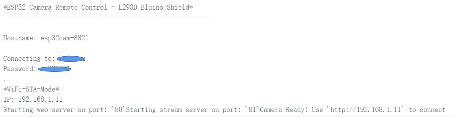
这时候,就可以通过这个IP地址在移动端查看摄像头显示的画面了。
测试与反思
在功能上面,通过实际测试,还要调整的有下面这些需求:
1、互动功能需要增加,就目前的移动与实时视频功能,家里的毛孩子兴趣不高。
2、视频传输的时候,发现质量不高,视频偏暗,需要增加一个补光灯。
3、供电问题需要优化。
在软件功能上,互动的功能已经写完,可以将一个激光发射器安装在舵机上,控制舵机的角度,来实现与毛孩子的互动。另外也找了个高亮LED来实现摄像头的补光功能。
视频演示
鱼丸明显对第一版的陪护很不满意。这也督促我赶紧要进行第二、第三版的迭代。希望下一版能让它有伸爪子的欲望。
附件


 他的勋章
他的勋章

许培享2023.11.28
还要看看一
腿毛利小五郎2023.10.25
666
每晚修仙2023.10.02
猫猫吓尿了。。。
9mm2023.09.22
666
_深蓝_2023.09.21
666