 返回首页
返回首页
 回到顶部
回到顶部
37款传感器与执行器的提法,在网络上广泛流传,其实Arduino能够兼容的传感器模块肯定是不止这37种的。鉴于本人手头积累了一些传感器和执行器模块,依照实践出真知(一定要动手做)的理念,以学习和交流为目的,这里准备逐一动手尝试系列实验,不管成功(程序走通)与否,都会记录下来—小小的进步或是搞不掂的问题,希望能够抛砖引玉。
【Arduino】168种传感器模块系列实验(资料代码+仿真编程+图形编程)
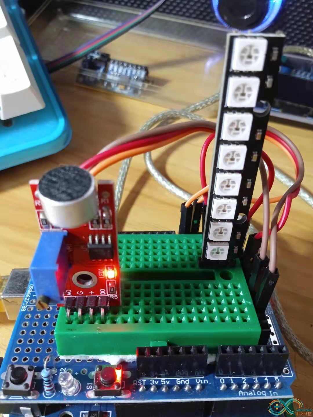
实验六十: 直条8位 WS2812B 5050 RGB LED内置全彩驱动彩灯模块
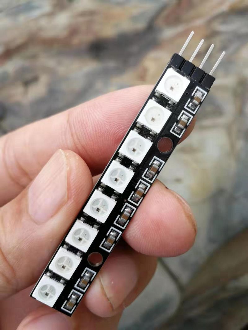
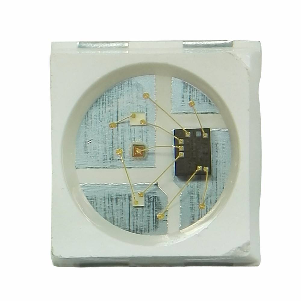
知识点:WS2812B芯片
是一个集控制电路与发光电路于一体的智能外控LED光源。其外型与一个5050LED灯珠相同,每个元件即为一个像素点。像素点内部包含了智能数字接口数据锁存信号整形放大驱动电路,还包含有高精度的内部振荡器和12V高压可编程定电流控制部分,有效保证了像素点光的颜色高度一致。数据协议采用单线归零码的通讯方式,像素点在上电复位以后,DIN端接受从控制器传输过来的数据,首先送过来的24bit数据被第一个像素点提取后,送到像素点内部的数据锁存器,剩余的数据经过内部整形处理电路整形放大后通过DO端口开始转发输出给下一个级联的像素点,每经过一个像素点的传输,信号减少24bit。像素点采用自动整形转发技术,使得该像素点的级联个数不受信号传送的限制,仅仅受限信号传输速度要求。
WS2812主要特点
1、智能反接保护,电源反接不会损坏IC。
2、IC控制电路与LED点光源公用一个电源。
3、控制电路与RGB芯片集成在一个5050封装的元器件中,构成一个完整的外控像素点。
4、内置信号整形电路,任何一个像素点收到信号后经过波形整形再输出,保证线路波形畸变不会累加。
5、内置上电复位和掉电复位电路。
6、每个像素点的三基色颜色可实现256级亮度显示,完成16777216种颜色的全真色彩显示,扫描频率不低于400Hz/s。
7、串行级联接口,能通过一根信号线完成数据的接收与解码。
8、任意两点传传输距离在不超过5米时无需增加任何电路。
9、当刷新速率30帧/秒时,级联数不小于1024点。
10、数据发送速度可达800Kbps。
11、光的颜色高度一致,性价比高。
【Arduino】168种传感器模块系列实验(资料代码+图形编程+仿真编程)
实验六十:直条8位 WS2812B 5050 RGB LED内置全彩驱动彩灯模块
项目三十八:音乐反应式 LED 灯条
实验开源代码
/*
【Arduino】168种传感器模块系列实验(资料代码+图形编程+仿真编程)
实验六十一:直条8位 WS2812B 5050 RGB LED内置全彩驱动彩灯模块
项目三十八:音乐反应式 LED 灯条
*/
#include <Adafruit_NeoPixel.h>
#include <math.h>
#define N_PIXELS 8
#define MIC_PIN A0
#define LED_PIN 6
#define SAMPLE_WINDOW 5
#define PEAK_HANG 24
#define PEAK_FALL 4
#define INPUT_FLOOR 10
#define INPUT_CEILING 50
byte peak = 16;
unsigned int sample;
byte Count = 0;
byte HangCount = 0;
Adafruit_NeoPixel strip = Adafruit_NeoPixel(N_PIXELS, LED_PIN, NEO_GRB + NEO_KHZ800);
void setup() {
Serial.begin(9600);
analogReference(EXTERNAL);
strip.setBrightness(22);
strip.show();
strip.begin();
}
float fscale( float originalMin, float originalMax, float newBegin, float newEnd, float inputValue, float curve) {
float OriginalRange = 0;
float NewRange = 0;
float zeroRefCurVal = 0;
float normalizedCurVal = 0;
float rangedValue = 0;
boolean invFlag = 0;
if (curve > 10) curve = 10;
if (curve < -10) curve = -10;
curve = (curve * -.1) ;
curve = pow(10, curve);
if (inputValue < originalMin) {
inputValue = originalMin;
}
if (inputValue > originalMax) {
inputValue = originalMax;
}
OriginalRange = originalMax - originalMin;
if (newEnd > newBegin) {
NewRange = newEnd - newBegin;
}
else
{
NewRange = newBegin - newEnd;
invFlag = 1;
}
zeroRefCurVal = inputValue - originalMin;
normalizedCurVal = zeroRefCurVal / OriginalRange; // normalize to 0 - 1 float
Serial.print(OriginalRange, DEC);
Serial.print(" ");
Serial.print(NewRange, DEC);
Serial.print(" ");
Serial.println(zeroRefCurVal, DEC);
Serial.println();
delay(10);
if (originalMin > originalMax ) {
return 0;
}
if (invFlag == 0) {
rangedValue = (pow(normalizedCurVal, curve) * NewRange) + newBegin;
}
else
{
rangedValue = newBegin - (pow(normalizedCurVal, curve) * NewRange);
}
return rangedValue;
}
void loop() {
unsigned long startMillis = millis();
float peakToPeak = 0;
unsigned int signalMax = 0;
unsigned int signalMin = 1023;
unsigned int c, y;
while (millis() - startMillis < SAMPLE_WINDOW)
{
sample = analogRead(MIC_PIN);
if (sample < 1024)
{
if (sample > signalMax)
{
signalMax = sample;
}
else if (sample < signalMin)
{
signalMin = sample;
}
}
}
peakToPeak = signalMax - signalMin;
for (int i = 0; i <= strip.numPixels() - 1; i++) {
strip.setPixelColor(i, Wheel(map(i, 0, strip.numPixels() - 1, 30, 150)));
}
c = fscale(INPUT_FLOOR, INPUT_CEILING, strip.numPixels(), 0, peakToPeak, 2);
if (c < peak) {
peak = c;
HangCount = 0;
}
if (c <= strip.numPixels()) {
drawLine(strip.numPixels(), strip.numPixels() - c, strip.Color(0, 0, 0));
}
y = strip.numPixels() - peak;
strip.setPixelColor(y - 1, Wheel(map(y, 0, strip.numPixels() - 1, 30, 150)));
strip.show();
if (HangCount > PEAK_HANG) {
if (++Count >= PEAK_FALL) {
peak++;
Count = 0;
}
}
else {
HangCount++;
}
}
void drawLine(uint8_t from, uint8_t to, uint32_t c) {
uint8_t fromTemp;
if (from > to) {
fromTemp = from;
from = to;
to = fromTemp;
}
for (int i = from; i <= to; i++) {
strip.setPixelColor(i, c);
}
}
uint32_t Wheel(byte WheelPos) {
if (WheelPos < 85) {
return strip.Color(WheelPos * 3, 255 - WheelPos * 3, 0);
}
else if (WheelPos < 170) {
WheelPos -= 85;
return strip.Color(255 - WheelPos * 3, 0, WheelPos * 3);
}
else {
WheelPos -= 170;
return strip.Color(0, WheelPos * 3, 255 - WheelPos * 3);
}
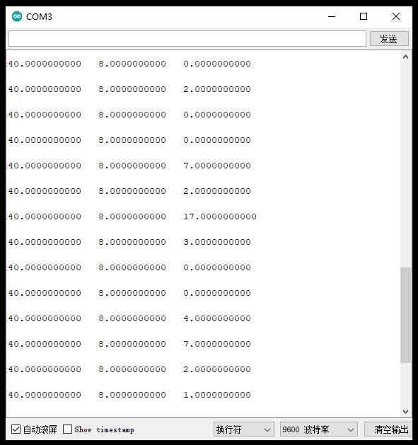
}实验串口返回情况
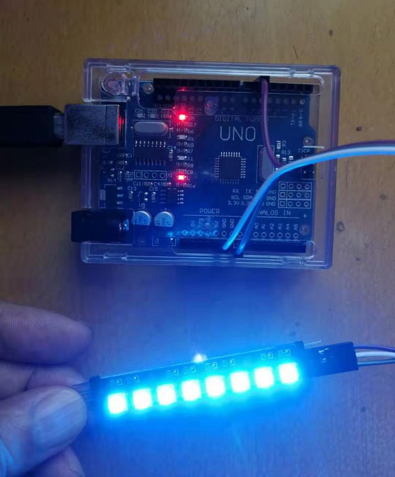
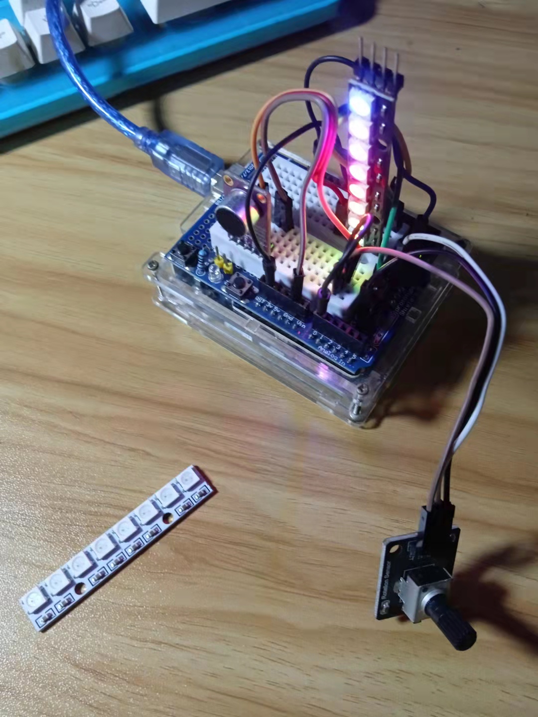
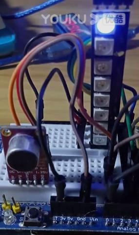
实验场景图
【Arduino】168种传感器模块系列实验(资料代码+图形编程+仿真编程)
实验六十:直条8位 WS2812B 5050 RGB LED内置全彩驱动彩灯模块
项目三十八:音乐反应式 LED 灯条(实验视频)
https://v.youku.com/v_show/id_XNTgwODQ3NzI5Mg==.html?spm=a2hcb.playlsit.page.1
【Arduino】168种传感器模块系列实验(资料代码+图形编程+仿真编程)
实验六十:直条8位 WS2812B 5050 RGB LED内置全彩驱动彩灯模块
项目三十九:16灯音乐反应式 LED 条
实验开源代码
/*
【Arduino】168种传感器模块系列实验(资料代码+图形编程+仿真编程)
实验六十一:直条8位 WS2812B 5050 RGB LED内置全彩驱动彩灯模块
项目三十九:16灯音乐反应式 LED 条
*/
#include <Adafruit_NeoPixel.h>
#include <math.h>
#define N_PIXELS 16
#define MIC_PIN A0
#define LED_PIN 6
#define SAMPLE_WINDOW 5
#define PEAK_HANG 24
#define PEAK_FALL 4
#define INPUT_FLOOR 10
#define INPUT_CEILING 50
byte peak = 16;
unsigned int sample;
byte Count = 0;
byte HangCount = 0;
Adafruit_NeoPixel strip = Adafruit_NeoPixel(N_PIXELS, LED_PIN, NEO_GRB + NEO_KHZ800);
void setup() {
Serial.begin(9600);
analogReference(EXTERNAL);
strip.setBrightness(22);
strip.show();
strip.begin();
}
float fscale( float originalMin, float originalMax, float newBegin, float newEnd, float inputValue, float curve) {
float OriginalRange = 0;
float NewRange = 0;
float zeroRefCurVal = 0;
float normalizedCurVal = 0;
float rangedValue = 0;
boolean invFlag = 0;
if (curve > 10) curve = 10;
if (curve < -10) curve = -10;
curve = (curve * -.1) ;
curve = pow(10, curve);
if (inputValue < originalMin) {
inputValue = originalMin;
}
if (inputValue > originalMax) {
inputValue = originalMax;
}
OriginalRange = originalMax - originalMin;
if (newEnd > newBegin) {
NewRange = newEnd - newBegin;
}
else
{
NewRange = newBegin - newEnd;
invFlag = 1;
}
zeroRefCurVal = inputValue - originalMin;
normalizedCurVal = zeroRefCurVal / OriginalRange; // normalize to 0 - 1 float
Serial.print(OriginalRange, DEC);
Serial.print(" ");
Serial.print(NewRange, DEC);
Serial.print(" ");
Serial.println(zeroRefCurVal, DEC);
Serial.println();
delay(10);
if (originalMin > originalMax ) {
return 0;
}
if (invFlag == 0) {
rangedValue = (pow(normalizedCurVal, curve) * NewRange) + newBegin;
}
else
{
rangedValue = newBegin - (pow(normalizedCurVal, curve) * NewRange);
}
return rangedValue;
}
void loop() {
unsigned long startMillis = millis();
float peakToPeak = 0;
unsigned int signalMax = 0;
unsigned int signalMin = 1023;
unsigned int c, y;
while (millis() - startMillis < SAMPLE_WINDOW)
{
sample = analogRead(MIC_PIN);
if (sample < 1024)
{
if (sample > signalMax)
{
signalMax = sample;
}
else if (sample < signalMin)
{
signalMin = sample;
}
}
}
peakToPeak = signalMax - signalMin;
for (int i = 0; i <= strip.numPixels() - 1; i++) {
strip.setPixelColor(i, Wheel(map(i, 0, strip.numPixels() - 1, 30, 150)));
}
c = fscale(INPUT_FLOOR, INPUT_CEILING, strip.numPixels(), 0, peakToPeak, 2);
if (c < peak) {
peak = c;
HangCount = 0;
}
if (c <= strip.numPixels()) {
drawLine(strip.numPixels(), strip.numPixels() - c, strip.Color(0, 0, 0));
}
y = strip.numPixels() - peak;
strip.setPixelColor(y - 1, Wheel(map(y, 0, strip.numPixels() - 1, 30, 150)));
strip.show();
if (HangCount > PEAK_HANG) {
if (++Count >= PEAK_FALL) {
peak++;
Count = 0;
}
}
else {
HangCount++;
}
}
void drawLine(uint8_t from, uint8_t to, uint32_t c) {
uint8_t fromTemp;
if (from > to) {
fromTemp = from;
from = to;
to = fromTemp;
}
for (int i = from; i <= to; i++) {
strip.setPixelColor(i, c);
}
}
uint32_t Wheel(byte WheelPos) {
if (WheelPos < 85) {
return strip.Color(WheelPos * 3, 255 - WheelPos * 3, 0);
}
else if (WheelPos < 170) {
WheelPos -= 85;
return strip.Color(255 - WheelPos * 3, 0, WheelPos * 3);
}
else {
WheelPos -= 170;
return strip.Color(0, WheelPos * 3, 255 - WheelPos * 3);
}
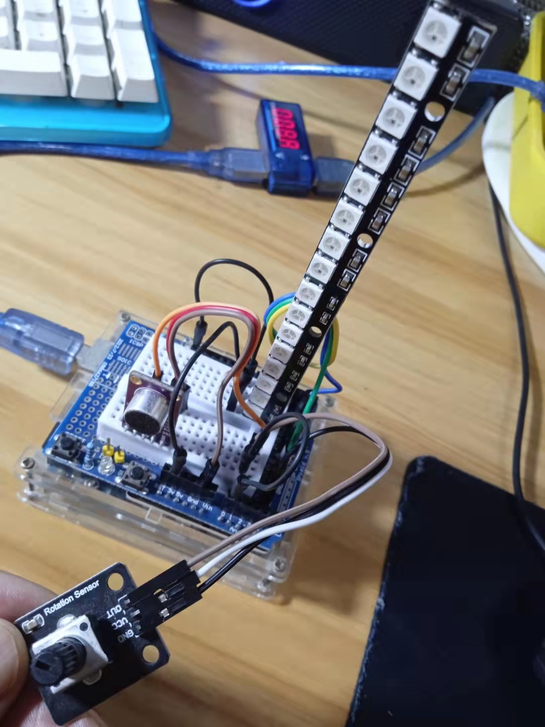
}实验场景图
【Arduino】168种传感器模块系列实验(资料代码+图形编程+仿真编程)
实验九十七: 0.96寸I2C IIC通信128*64显示器 OLED液晶屏模块
项目三十五:十六位音乐反应式 LED 灯条(实验视频)
https://v.youku.com/v_show/id_XNTgwODQ4Njk2MA==.html?spm=a2hcb.playlsit.page.1
【Arduino】168种传感器模块系列实验(资料代码+图形编程+仿真编程)
实验六十:直条16位 WS2812B 5050 RGB LED内置全彩驱动彩灯模块
项目四十:十六位音乐频谱灯条
实验开源代码
/*
  【Arduino】168种传感器模块系列实验(资料代码+图形编程+仿真编程)
  实验六十一:直条16位 WS2812B 5050 RGB LED内置全彩驱动彩灯模块
  项目四十:十六位音乐频谱灯条
*/

#include "FastLED.h"

#define OCTAVE 1 //   // Group buckets into octaves  (use the log output function LOG_OUT 1)
#define OCT_NORM 0 // Don't normalise octave intensities by number of bins
#define FHT_N 256 // set to 256 point fht
#include <FHT.h> // include the library
//int noise[] = {204,188,68,73,150,98,88,68}; // noise level determined by playing pink noise and seeing levels [trial and error]{204,188,68,73,150,98,88,68}


// int noise[] = {204,190,108,85,65,65,55,60}; // noise for mega adk
int noise[] = {204,195,100,90,85,80,75,75}; // noise for NANO
//int noise[] = {204,198,100,85,85,80,80,80};
float noise_fact[] = {15, 7, 1.5, 1, 1.2, 1.4, 1.7,3}; // noise level determined by playing pink noise and seeing levels [trial and error]{204,188,68,73,150,98,88,68}
float noise_fact_adj[] = {15, 7, 1.5, 1, 1.2, 1.4, 1.7,3}; // noise level determined by playing pink noise and seeing levels [trial and error]{204,188,68,73,150,98,88,68}


#define LED_PIN     6
#define LED_TYPE    WS2812
#define COLOR_ORDER GRB


// Params for width and height
const uint8_t kMatrixWidth = 8;
const uint8_t kMatrixHeight = 8;//----------was 27
//#define NUM_LEDS (kMatrixWidth * kMatrixHeight)
#define NUM_LEDS    64

CRGB leds[NUM_LEDS];

int counter2=0;


void setup() {
Serial.begin(9600);
  delay(1000);
  FastLED.addLeds<LED_TYPE, LED_PIN, COLOR_ORDER>(leds, NUM_LEDS).setCorrection( TypicalLEDStrip );

  FastLED.setBrightness (33);
  fill_solid(leds, NUM_LEDS, CRGB::Black);
  FastLED.show();
// TIMSK0 = 0; // turn off timer0 for lower jitter
  ADCSRA = 0xe5; // set the adc to free running mode
  ADMUX = 0x40; // use adc0
  DIDR0 = 0x01; // turn off the digital input for adc0

}


void loop() {
int prev_j[8];
int beat=0;
int prev_oct_j;
int counter=0;
int prev_beat=0;
int led_index=0;
int saturation=0;
int saturation_prev=0;
int brightness=0;
int brightness_prev=0;

 while (1) { // reduces jitter

      cli();  // UDRE interrupt slows this way down on arduino1.0

  for (int i = 0 ; i < FHT_N ; i++) { // save 256 samples
      while (!(ADCSRA & 0x10)); // wait for adc to be ready
      ADCSRA = 0xf5; // restart adc
      byte m = ADCL; // fetch adc data
      byte j = ADCH;
      int k = (j << 8) | m; // form into an int
      k -= 0x0200; // form into a signed int
      k <<= 6; // form into a 16b signed int
      fht_input[i] = k; // put real data into bins
    }
    fht_window(); // window the data for better frequency response
    fht_reorder(); // reorder the data before doing the fht
    fht_run(); // process the data in the fht
    fht_mag_octave(); // take the output of the fht  fht_mag_log()

   // every 50th loop, adjust the volume accourding to the value on A2 (Pot)
    if (counter >= 50) {
      ADMUX = 0x40 | (1 & 0x07); // set admux to look at Analogpin A1 - Master Volume


      while (!(ADCSRA & 0x10)); // wait for adc to be ready
      ADCSRA = 0xf5; // restart adc
  delay(10);
      while (!(ADCSRA & 0x10)); // wait for adc to be ready
      ADCSRA = 0xf5; // restart adc
      byte m = ADCL; // fetch adc data
      byte j = ADCH;
      int k = (j << 8) | m; // form into an int
      float master_volume=(k+0.1)/1000 +.75;  // so the valu will be between ~0.5 and 1.---------------------+.75 was .5
  Serial.println (master_volume);


      for (int i=1; i<8; i++) {
          noise_fact_adj[i]=noise_fact[i]*master_volume;
      }

      ADMUX = 0x40 | (0 & 0x07); // set admux back to look at A0 analog pin (to read the microphone input
      counter = 0;
    }

    sei();
    counter++;


    // End of Fourier Transform code - output is stored in fht_oct_out[i].

    // i=0-7 frequency (octave) bins (don't use 0 or 1), fht_oct_out[1]= amplitude of frequency for bin 1
    // for loop a) removes background noise average and takes absolute value b) low / high pass filter as still very noisy
    // c) maps amplitude of octave to a colour between blue and red d) sets pixel colour to amplitude of each frequency (octave)

    for (int i = 1; i < 8; i++) {  // goes through each octave. skip the first 1, which is not useful

      int j;
      j = (fht_oct_out[i] - noise[i]); // take the pink noise average level out, take the asbolute value to avoid negative numbers
      if (j<10) {j=0;}
      j= j*noise_fact_adj[i];

      if (j<10) {j=0;}
      else {
        j= j*noise_fact_adj[i];
        if (j>180) {
          if (i>=7) {
            beat+=2;
          }
          else {
            beat+=1;
          }
        }
        j=j/30;
        j=j*30; // (force it to more discrete values)
      }

      prev_j[i]=j;

//     Serial.print(j);
//     Serial.print(" ");


// this fills in 11 LED's with interpolated values between each of the 8 OCT values
       if (i>=2) {
        led_index=2*i-3;
        prev_oct_j=(j+prev_j[i-1])/2;

        saturation=constrain(j+50, 0,255);//-----------50 was 30
        saturation_prev=constrain(prev_oct_j+50, 0,255);
        brightness=constrain(j, 0,255);
        brightness_prev=constrain(prev_oct_j, 0,255);
if (brightness==255) {
  saturation=50;
  brightness=200;
}
if (brightness_prev==255) {
  saturation_prev=50;
  brightness_prev=200;
}


        for (uint8_t y=0;y<kMatrixHeight;y++){
          leds[XY(led_index-1,y)] = CHSV(j+y*30,saturation, brightness);
          if (i>2){
            prev_oct_j=(j+prev_j[i-1])/2;
            leds[ XY(led_index-2,y)]=CHSV(prev_oct_j+y*30,saturation_prev, brightness_prev);
          }
        }
       }
    }


      if (beat>=7) {
          fill_solid(leds, NUM_LEDS, CRGB::Gray);
          FastLED.setBrightness(200);


      }
    else {
      if (prev_beat!=beat) {
        FastLED.setBrightness(40+beat*beat*5);
        prev_beat=beat;
      }

    }

    FastLED.show();
    if (beat) {
      counter2+=((beat+4)/2-2);
      if (counter2<0) {counter2=1000;}
      if (beat>3 && beat<7) {
         FastLED.delay (20);
      }
      beat=0;
    }

// Serial.println();
 }
}


// Param for different pixel layouts
const bool    kMatrixSerpentineLayout = false;
// Set 'kMatrixSerpentineLayout' to false if your pixels are
// laid out all running the same way, like this:

// Set 'kMatrixSerpentineLayout' to true if your pixels are
// laid out back-and-forth, like this:

uint16_t XY( uint8_t x, uint8_t y)
{
  uint16_t i;

  if( kMatrixSerpentineLayout == false) {
    i = (y * kMatrixWidth) + x;
  }

  if( kMatrixSerpentineLayout == true) {
    if( y & 0x01) {
      // Odd rows run backwards
      uint8_t reverseX = (kMatrixWidth - 1) - x;
      i = (y * kMatrixWidth) + reverseX;

    } else {
      // Even rows run forwards
      i = (y * kMatrixWidth) + x;

    }
  }

  i=(i+counter2)%NUM_LEDS;
  return i;
}
【Arduino】168种传感器模块系列实验(资料代码+图形编程+仿真编程)
实验六十:直条16位 WS2812B 5050 RGB LED内置全彩驱动彩灯模块
项目四十:十六位音乐频谱灯条
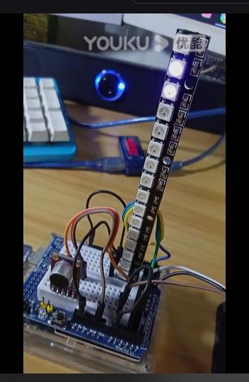
实验视频剪辑
https://v.youku.com/v_show/id_XNTgwODYxOTI5Ng==.html?spm=a2hcb.playlsit.page.1
【Arduino】168种传感器模块系列实验(资料代码 +图形编程 +仿真编程)
实验六十:直条16位 WS2812B 5050 RGB LED内置全彩驱动彩灯模块
项目四十一:快速哈特利变换FHT音乐反应灯条
实验开源代码
/*
  【Arduino】168种传感器模块系列实验(资料代码 +图形编程 +仿真编程)
  实验六十一:直条16位 WS2812B 5050 RGB LED内置全彩驱动彩灯模块
  项目四十一:快速哈特利变换FHT音乐反应灯条
*/

/*
  这是带有 FastLED 的 FHT 库的项目
  FHT 库位于 http://wiki.openmusiclabs.com/wiki/ArduinoFHT
  开始的例子是:
  https://github.com/TJC/arduino/blob/master/fhttest/fhttest.cpp

  注意:如果您使用的是由 3.3V 信号供电的麦克风,例如 Sparkfun MEMS 麦克风,则将 3.3V 连接到 AREF 引脚。
  还要确保取消对 analogReference(EXTERNAL); 的注释。 在设置()中。

  在线频率发生器 测试:http://onlinetonegenerator.com/frequency-sweep-generator.html
*/


#define qsubd(x, b) ((x>b)?wavebright:0)                     // A digital unsigned subtraction macro. if result <0, then => 0. Otherwise, take on fixed value.
#define qsuba(x, b) ((x>b)?x-b:0)                            // Unsigned subtraction macro. if result <0, then => 0.

#define wavebright 128                                        // qsubd result will be this value if subtraction is >0.

#include "FastLED.h"                                          // FastLED library. Preferably the latest copy of FastLED 2.1.

#if FASTLED_VERSION < 3001000
#error "Requires FastLED 3.1 or later; check github for latest code."
#endif

// Fixed definitions cannot change on the fly.
#define LED_DT 6                                             // Data pin to connect to the strip.
//#define LED_CK 11                                             // Clock pin for APA102 or WS2801
#define COLOR_ORDER GRB                                       // It's GRB for WS2812
#define LED_TYPE WS2812B                                       // What kind of strip are you using (APA102, WS2801 or WS2812B)
#define NUM_LEDS 16                                        // Number of LED's.

// Initialize changeable global variables.
uint8_t max_bright = 255;                                     // Overall brightness definition. It can be changed on the fly.

struct CRGB leds[NUM_LEDS];                                   // Initialize our LED array.


#define LOG_OUT 1

#define FHT_N 256                                             // Set to 256 point fht.
#define inputPin A0
//#define potPin A4

#include <FHT.h>                                              // FHT library


uint8_t hueinc = 0;                                               // A hue increment value to make it rotate a bit.
uint8_t micmult = 25;
uint8_t fadetime = 900;
uint8_t noiseval = 25;                                        // Increase this to reduce sensitivity. 30 seems best for quiet

void setup() {
  analogReference(EXTERNAL);                                  // Connect 3.3V to AREF pin for any microphones using 3.3V
  Serial.begin(9600);                                        // use the serial port

  LEDS.addLeds<LED_TYPE, LED_DT, COLOR_ORDER>(leds, NUM_LEDS);
  //  LEDS.addLeds<LED_TYPE, LED_DT, LED_CK, COLOR_ORDER>(leds, NUM_LEDS);

  FastLED.setBrightness(max_bright);
  set_max_power_in_volts_and_milliamps(5, 500);               // FastLED Power management set at 5V, 500mA.
}


void loop() {
  //    noiseval = map(analogRead(potPin), 0, 1023, 16, 48);          // Adjust sensitivity of cutoff.
  EVERY_N_MILLISECONDS(13) {
    fhtsound();
  }
  show_at_max_brightness_for_power();

  Serial.println(LEDS.getFPS(), DEC);         // Display frames per second on the serial monitor.
  Serial.println(" ");          // Display frames per second on the serial monitor.
  Serial.println(analogRead(inputPin));       // print as an ASCII-encoded decimal         */

}


void fhtsound() {
  // hueinc++;                                                   // A cute little hue incrementer.
  GetFHT();                                                   // Let's take FHT_N samples and crunch 'em.

  for (int i = 0; i < NUM_LEDS; i++) {                        // Run through the LED array.

    int tmp = qsuba(fht_log_out[2 * i + 2], noiseval);       // Get the sample and subtract the 'quiet' normalized values, but don't go < 0.
    if (tmp > (leds[i].r + leds[i].g + leds[i].b) / 2)          // Refresh an LED only when the intensity is low
      leds[i] = CHSV((i * 4) + tmp * micmult, 255, tmp * micmult); // Note how we really cranked up the tmp value to get BRIGHT LED's. Also increment the hue for fun.
    leds[i].nscale8(fadetime);                                     // Let's fade the whole thing over time as well.
  }
} // fhtsound()


void GetFHT() {
  cli();
  for (int i = 0 ; i < FHT_N ; i++) fht_input[i] = analogRead(inputPin);
  sei();

  fht_window();                                               // Window the data for better frequency response.
  fht_reorder();                                              // Reorder the data before doing the fht.
  fht_run();                                                  // Process the data in the fht.
  fht_mag_log();
} // GetFHT()
【Arduino】168种传感器模块系列实验(资料代码 +图形编程 +仿真编程)
实验六十一:直条16位 WS2812B 5050 RGB LED内置全彩驱动彩灯模块
项目四十一:快速哈特利变换FHT音乐反应灯条
实验视频剪辑
https://v.youku.com/v_show/id_XNTgwODY0ODEyOA==.html?firsttime=0
【花雕动手做】有趣好玩的音乐可视化系列小项目(04)---WS2812条灯
项目之一: 使用KY—038声音模块的阙值触发WS2812节奏灯条
实验开源代码
/*
  【花雕动手做】有趣好玩的音乐可视化系列小项目(04)---WS2812条灯
  项目之一: 使用KY—038声音模块的阙值触发WS2812节奏灯条
*/

#include<FastLED.h>
#define LED_PIN 6
#define NUM_LEDS 8

CRGB leds[NUM_LEDS];
uint8_t hue = 0;
int soundsensor = 7;

void setup() {
  delay(2000);
  Serial.begin(9600);
  FastLED.addLeds<WS2812B, LED_PIN, GRB>(leds, NUM_LEDS);
  FastLED.setBrightness(255);
  pinMode(soundsensor, INPUT);
}

void loop() {
  int sensval = digitalRead(soundsensor);

  if (sensval == 1) {
    Serial.println("ON");
    leds[0] = CRGB :: Red;
    fill_solid(leds, NUM_LEDS, CRGB :: Blue);
    rainbow_moving();
    FastLED.show();
    delay(10);
  }
  else {
    leds[0] = CRGB :: Black;
    fill_solid(leds, NUM_LEDS, CRGB :: Black);
    FastLED.show();
    delay(10);
  }
}

void rainbow_moving() {
  for (int i = 0; i < NUM_LEDS; i++) {
    leds[i] = CHSV(hue + (i * 10), 255, 255);
  }
  EVERY_N_MILLISECONDS(10) {
    hue++;
  }
}
【花雕动手做】有趣好玩的音乐可视化系列小项目(04)---WS2812条灯
项目之一: 使用KY—038声音模块的阙值触发WS2812节奏灯条
实验场景图
【花雕动手做】有趣好玩的音乐可视化系列小项目(04)---WS2812条灯
项目之一: 使用KY—038声音模块的阙值触发WS2812节奏灯条
实验视频剪辑
https://v.youku.com/v_show/id_XNTgxMTgxMjMwOA==.html?firsttime=0


 他的勋章
他的勋章

9mm2023.08.08
666