 返回首页
返回首页
 回到顶部
回到顶部
37款传感器与执行器的提法,在网络上广泛流传,其实Arduino能够兼容的传感器模块肯定是不止这37种的。鉴于本人手头积累了一些传感器和执行器模块,依照实践出真知(一定要动手做)的理念,以学习和交流为目的,这里准备逐一动手尝试系列实验,不管成功(程序走通)与否,都会记录下来—小小的进步或是搞不掂的问题,希望能够抛砖引玉。
【Arduino】168种传感器模块系列实验(资料代码+仿真编程+图形编程)
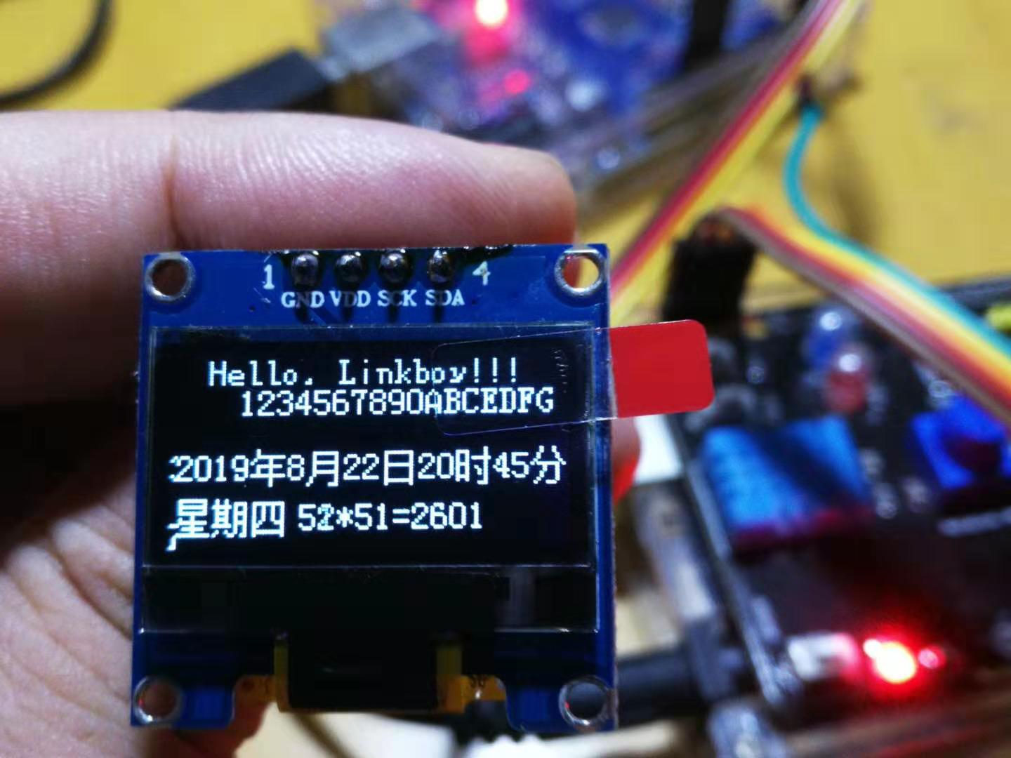
实验九十三:0.96寸I2C IIC通信128*64显示器 OLED液晶屏模块
【Arduino】168种传感器模块系列实验(资料代码+图形编程+仿真编程)
实验九十三: 0.96寸I2C IIC通信128*64显示器 OLED液晶屏模块
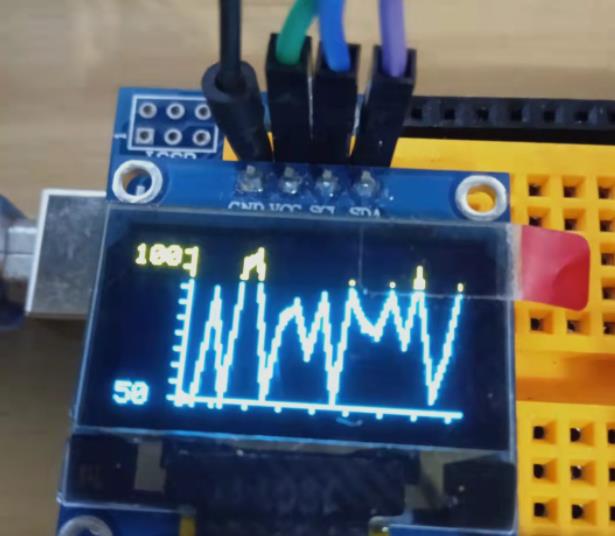
项目三十六:以单绘图模式绘制笛卡尔图
实验开源代码
/*
  【Arduino】168种传感器模块系列实验(资料代码+图形编程+仿真编程)
  实验九十七: 0.96寸I2C IIC通信128*64显示器 OLED液晶屏模块
  项目三十六:以单绘图模式绘制笛卡尔图
  实验接线方法:
  oled模块    Ardunio Uno
  GND---------GND接地线
  VCC---------5V 接电源
  SDA---------A4
  SCL ------- A5
*/

#include <Arduino.h>
#include <OLED_SSD1306_Chart.h>
#include <Adafruit_I2CDevice.h> //Include this to avoid compile errors in Platformio

#define SCREEN_WIDTH 128 // OLED display width, in pixels
#define SCREEN_HEIGHT 64 // OLED display height, in pixels

// Declaration for an SSD1306 display connected to I2C (SDA, SCL pins)
#define OLED_RESET -1 // Reset pin # (or -1 if sharing Arduino reset pin)

#define BAUDRATE 9600

#define SDA_PIN A4
#define SCL_PIN A5

OLED_SSD1306_Chart display(SCREEN_WIDTH, SCREEN_HEIGHT, &Wire, OLED_RESET);

char actualThickness;

void setup()
{
  // put your setup code here, to run once:
#if defined ESP8266
  Wire.begin(SDA_PIN, SCL_PIN);
#else
  Wire.begin();
#endif

  display.begin(SSD1306_SWITCHCAPVCC, 0x3c);
  display.clearDisplay();
  display.setChartCoordinates(0, 60);      //Chart lower left coordinates (X, Y)
  display.setChartWidthAndHeight(123, 55); //Chart width = 123 and height = 60
  display.setXIncrement(5);                //Distance between Y points will be 5px
  display.setYLimits(50, 100);             //Ymin = 0 and Ymax = 100
  display.setYLimitLabels("50", "100");    //Setting Y axis labels
  display.setYLabelsVisible(true);
  display.setAxisDivisionsInc(12, 6);    //Each 12 px a division will be painted in X axis and each 6px in Y axis
  display.setPlotMode(SINGLE_PLOT_MODE); //Set single plot mode
  // display.setPointGeometry(POINT_GEOMETRY_CIRCLE);
  actualThickness = NORMAL_LINE;
  display.setLineThickness(actualThickness);
  display.drawChart(); //Update the buffer to draw the cartesian chart
  display.display();
}

void loop()
{
  // put your main code here, to run repeatedly:
  auto value = random(50) + 50;
  if (!display.updateChart(value)) //Value between Ymin and Ymax will be added to chart
  {
    display.clearDisplay(); //If chart is full, it is drawn again
    if (actualThickness == NORMAL_LINE)
    {
      actualThickness = LIGHT_LINE;
    }
    else if (actualThickness == LIGHT_LINE)
    {
      actualThickness = NORMAL_LINE;
    }
    display.setLineThickness(actualThickness);
    display.drawChart();
  }
  delay(100);
}
Arduino实验场景图
【Arduino】168种传感器模块系列实验(资料代码+图形编程+仿真编程)
实验九十三: 0.96寸I2C IIC通信128*64显示器 OLED液晶屏模块
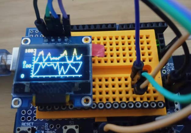
项目三十七:双绘图模式绘制笛卡尔图表
实验开源代码
/*
  【Arduino】168种传感器模块系列实验(资料代码+图形编程+仿真编程)
  实验九十七: 0.96寸I2C IIC通信128*64显示器 OLED液晶屏模块
  项目三十七:双绘图模式绘制笛卡尔图表
  实验接线方法:
  oled模块    Ardunio Uno
  GND---------GND接地线
  VCC---------5V 接电源
  SDA---------A4
  SCL ------- A5
*/

#include <Arduino.h>
#include <OLED_SSD1306_Chart.h>
#include <Adafruit_I2CDevice.h>

#define SCREEN_WIDTH 128 // OLED display width, in pixels
#define SCREEN_HEIGHT 64 // OLED display height, in pixels

// Declaration for an SSD1306 display connected to I2C (SDA, SCL pins)
#define OLED_RESET -1 // Reset pin # (or -1 if sharing Arduino reset pin)

#define BAUDRATE 9600

#define SDA_PIN A4
#define SCL_PIN A5

OLED_SSD1306_Chart display(SCREEN_WIDTH, SCREEN_HEIGHT, &Wire, OLED_RESET);

bool mid_line_visible = false;

void setup()
{
// put your setup code here, to run once:
#if defined ESP8266
  Wire.begin(SDA_PIN, SCL_PIN);
#else
  Wire.begin();
#endif

  display.begin(SSD1306_SWITCHCAPVCC, 0x3c);
  display.clearDisplay();
  display.setChartCoordinates(0, 60);      //Chart lower left coordinates (X, Y)
  display.setChartWidthAndHeight(123, 60); //Chart width = 123 and height = 60
  display.setXIncrement(5);                //Distance between Y points will be 5px
  display.setYLimits(0, 100);              //Ymin = 0 and Ymax = 100 for first chart
  display.setYLimits(0, 100, 1);           //Ymin = 0 and Ymax = 100 for second chart
  display.setYLimitLabels("0", "100");
  display.setYLimitLabels("0", "100", 1);
  display.setAxisDivisionsInc(12, 6); //Each 12 px a division will be painted in X axis and each 6px in Y axis
  display.setYLabelsVisible(true);
  display.setPlotMode(DOUBLE_PLOT_MODE); //Set double plot mode
  display.setMidLineVisible(mid_line_visible);
  display.setLineThickness(LIGHT_LINE);
  display.setLineThickness(NORMAL_LINE, 1);
  display.drawChart(); //Update the buffer to draw the cartesian chart
  display.display();
}

void loop()
{
  // put your main code here, to run repeatedly:
  auto value0 = random(100);
  auto value1 = random(100);
  if (!display.updateChart(value0, value1)) //Value between Ymin and Ymax will be added to chart
  {
    display.clearDisplay(); //If chart is full, it is drawn again
    mid_line_visible = !mid_line_visible;
    display.setMidLineVisible(mid_line_visible);
    display.drawChart();
  }
  delay(100);
}
Arduino实验场景图
【Arduino】168种传感器模块系列实验(资料代码+图形编程+仿真编程)
实验九十三: 0.96寸I2C IIC通信128*64显示器 OLED液晶屏模块
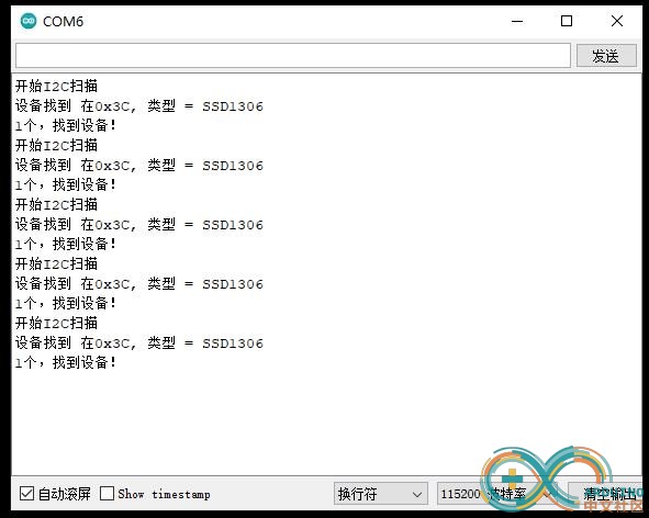
项目三十八:使用 BitBang_I2C 库扫描和识别 I2C 总线上的设备
实验开源代码
/*
  【Arduino】168种传感器模块系列实验(资料代码+图形编程+仿真编程)
  实验九十七: 0.96寸I2C IIC通信128*64显示器 OLED液晶屏模块
  项目三十八:使用 BitBang_I2C 库扫描和识别 I2C 总线上的设备
  实验接线方法:
  oled模块    Ardunio Uno
  GND---------GND接地线
  VCC---------5V 接电源
  SDA---------A4
  SCL ------- A5
*/

//使用Bit Bang I2C 库。你可以在这里找到它:
// https://github.com/bitbank2/BitBang_I2C
#include <BitBang_I2C.h>

// Arbitrary pins I used for testing with an ATmega328p
// Define as -1, -1 to use the Wire library over the default I2C interface
#define SDA_PIN A4
#define SCL_PIN A5
// M5Stack Atom Grove connector pin assignments
//#define SDA_PIN 32
//#define SCL_PIN 26
// M5Stack Atom internal I2C connected to the IMU
//#define SDA_PIN 25
//#define SCL_PIN 21
// M5Stack Core2 internal I2C
//#define SDA_PIN 21
//#define SCL_PIN 22
//
// If you don't need the explicit device names displayed, disable this code by
// commenting out the next line
//
#define SHOW_NAME
#ifdef SHOW_NAME
const char *szNames[]  = {"Unknown","SSD1306","SH1106","VL53L0X","BMP180", "BMP280","BME280",
                "MPU-60x0", "MPU-9250", "MCP9808","LSM6DS3", "ADXL345", "ADS1115","MAX44009",
                "MAG3110", "CCS811", "HTS221", "LPS25H", "LSM9DS1","LM8330", "DS3231", "LIS3DH",
                "LIS3DSH","INA219","SHT3X","HDC1080","MPU6886","BME680", "AXP202", "AXP192", "24AA02XEXX",
                "DS1307", "MPU688X", "FT6236G", "FT6336G", "FT6336U", "FT6436", "BM8563"};
#endif

BBI2C bbi2c;

void setup() {
  Serial.begin(115200);
  memset(&bbi2c, 0, sizeof(bbi2c));
  bbi2c.bWire = 0; // use bit bang, not wire library
  bbi2c.iSDA = SDA_PIN;
  bbi2c.iSCL = SCL_PIN;
  I2CInit(&bbi2c, 100000L);
  delay(100); // allow devices to power up
}

void loop() {
uint8_t map[16];
uint8_t i;
int iDevice, iCount;

  Serial.println("开始I2C扫描");
  I2CScan(&bbi2c, map); // get bitmap of connected I2C devices
  if (map[0] == 0xfe) // something is wrong with the I2C bus
  {
    Serial.println("I2C 引脚不正确或总线被坏设备拉低;无法运行扫描");
  }
  else
  {
    iCount = 0;
    for (i=1; i<128; i++) // skip address 0 (general call address) since more than 1 device can respond
    {
      if (map[i>>3] & (1 << (i & 7))) // device found
      {
        iCount++;
        Serial.print("设备找到 在0x");
        Serial.print(i, HEX);
        iDevice = I2CDiscoverDevice(&bbi2c, i);
        Serial.print(", 类型 = ");
  #ifdef SHOW_NAME
        Serial.println(szNames[iDevice]); // show the device name as a string
  #else
        Serial.println(iDevice); // show the device name as the enum index
  #endif
      }
    } // for i
    Serial.print(iCount, DEC);
    Serial.println("个,找到设备!");
  }
  delay(5000);
}
实验串口返回情况
BitBang_I2C库
https://github.com/bitbank2/BitBang_I2C
这段代码的目的是提供一个简单的 C 库,它可以在任何系统上的任何 2 个 GPIO 引脚上对 I2C 协议进行 bit-bang。除了标准 GPIO 功能之外,I2C 协议不需要引脚的任何特殊功能。写它的原因是为了轻松访问各种不一定公开 I2C 接口的微控制器上的 I2C 设备。这在包括 AVR、ESP32 和 nRF5 微控制器在内的各种项目中都派上用场。
引脚访问函数可以是本机版本的封装函数(例如在 nRF5 SDK 上) 在 AVR 微控制器上,digitalWrite/digitalRead/pinMode 函数有点慢,因为它们根据表检查引脚编号并执行其他任务。该库包含加快速度的逻辑。通过将引脚编号指定为端口名称 + 位,库将在 AVR 微控制器上运行得更快。例如,在 Arduino Uno (ATmega328P) 上,I/O 引脚 9 实际上是 I/O 端口 B,位 1。要使用直接引脚方法,您可以将引脚编号指定为0xB1。在 ATtiny85 上,这是唯一支持的引脚编号,因此不会链接到 Wire 库(以节省 FLASH 空间)。
这个最新版本允许您将此库用于位爆炸 I2C 或间接使用 Wire 库。由于每个 BBI2C 对象都是独立的,因此您可以拥有任意数量的总线,在 bit-bang 和硬件 I2C 的任意组合上运行。
用法:
首先使用 SDA/SCL 所需的引脚编号以及所需的时钟频率初始化 BBI2C 结构。bWire 标志告诉库在设置为 true 时使用硬件 I2C。如果使用硬件 I2C(线库),可以将引脚编号设置0xff为使用默认 I2C 引脚或支持多个 I2C 总线的系统上的特定引脚。400Khz 以上的频率是可能的,但不一定准确。幸运的是,I2C 设备并不真正关心确切的时钟频率,只关心信号在给定周期内是稳定的。
例如:
```cpp
<p>BBI2C bbi2c;</p><p>bbi2c.bWire = 0 ; //使用位敲击</p><p>bbi2c.iSDA = 10 ; // GPIO 引脚 10 上的 SDA </p><p>bbi2c.iSCL = 11 ; // GPIO 引脚 11 上的 SCL </p><p>I2CInit (&bbi2c, 100000 ); // SDA=pin 10, SCL=pin 11, 100K 时钟</p>
```
与其公开启动和停止 I2C 事务的函数,我决定通过提供隐藏 I2C 协议细节的复合函数来简化它。为了扫描设备的 I2C 总线,我提供了 I2CScan() 函数,该函数返回一个位图(16 字节 x 8 位),其中为它找到的每个设备设置了一个位。像这样调用它:
```cpp
unsigned char ucMap[16];
I2CScan(&bbi2c, ucMap);
```
要检测单个地址是否处于活动状态,请使用
```cpp
I2CTest(addr)
```
要识别设备,请使用
```cpp
I2CDiscoverDevice(uint8_t iAddress)
```
要对 I2C 设备读取和写入数据,请使用以下函数:
```cpp
<p>I2CRead (&bbi2c, uint8_t u8Address, uint8_t *pu8Data, int iLength);</p><p>I2CReadRegister (&bbi2c, uint8_t iAddr, uint8_t u8Register, uint8_t *pData, int iLen);</p><p>I2CWrite (&bbi2c, uint8_t iAddr, uint8_t *pData, int iLen);</p>
```
目前有 29 台设备被发现功能识别:
SSD1306
SH1106
VL53L0X
BMP180
BMP280
BME280
BME680
MPU6000
MPU9250
MCP9808
LSM6DS3
ADXL345
ADS1115
MAX44009
MAG3110
CCS811
HTS221
LPS25H
LSM9DS1
LM8330
DS3231
DS1307
LIS3DH
LIS3DSH
INA219
SHT3X
HDC1080
AXP192
AXP202
24AAXXXE64


 他的勋章
他的勋章

hacker_2023.07.27
666