 返回首页
返回首页
 回到顶部
回到顶部
37款传感器与模块的提法,在网络上广泛流传,其实Arduino能够兼容的传感器模块肯定是不止37种的。鉴于本人手头积累了一些传感器和模块,依照实践出真知(一定要动手做)的理念,以学习和交流为目的,这里准备逐一动手试试做实验,不管成功与否,都会记录下来---小小的进步或是搞不定的问题,希望能够抛砖引玉。
【Arduino】108种传感器模块系列实验(资料+代码+图形+仿真)
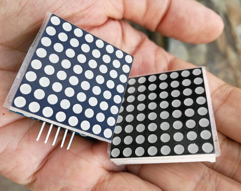
实验二十二:MAX7219点阵显示模块(8X8 LED共阴屏幕)
【Arduino】168种传感器模块系列实验(资料代码+仿真编程+图形编程)
实验二十二:MAX7219点阵显示模块(8X8 LED共阴)
项目二十八:上下碰碰球
实验开源代码
/*
【Arduino】168种传感器模块系列实验(资料代码+仿真编程+图形编程)
实验二十二:MAX7219点阵显示模块(8X8 LED共阴)
项目二十八:上下碰碰球
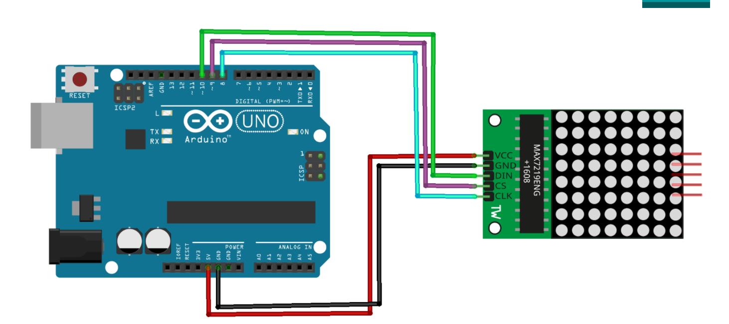
接脚连线:
MAX7219 UNO
VCC →→→→→ 5V
GND →→→→→ GND
DIN →→→→→ D12(数据,数据接收引脚)
CS →→→→→ D11(负载,命令接收引脚)
CLK →→→→→ D10(时钟,时钟引脚)
*/
#include <LedControl.h>
const int DIN_PIN = 12;
const int CS_PIN = 11;
const int CLK_PIN = 10;
const uint64_t IMAGES[] = {
0xff000001010000ff, 0xff000003030000ff, 0xff000006060000ff,
0xff00000c0c0000ff, 0xff000018180000ff, 0xff000030300000ff,
0xff000060600000ff, 0xff0000c0c00000ff, 0xff000080800000ff,
0xff0000c0c00000ff, 0xff000060600000ff, 0xff000018180000ff,
0xff00000c0c0000ff, 0xff000006060000ff, 0xff000003030000ff,
0xff000001010000ff
};
const int IMAGES_LEN = sizeof(IMAGES) / 8;
LedControl display = LedControl(DIN_PIN, CLK_PIN, CS_PIN);
void setup() {
display.clearDisplay(0);
display.shutdown(0, false);
display.setIntensity(0, 10);
}
void displayImage(uint64_t image) {
for (int i = 0; i < 8; i++) {
byte row = (image >> i * 8) & 0xFF;
for (int j = 0; j < 8; j++) {
display.setLed(0, i, j, bitRead(row, j));
}
}
}
int i = 0;
void loop() {
displayImage(IMAGES[i]);
if (++i >= IMAGES_LEN ) {
i = 0;
}
delay(100);
}
【Arduino】168种传感器模块系列实验(资料代码+仿真编程+图形编程)
实验二十二:MAX7219点阵显示模块(8X8 LED共阴)
项目二十九:满屏矩阵变换
实验开源代码
/*
  【Arduino】168种传感器模块系列实验(资料代码+仿真编程+图形编程)
  实验二十二:MAX7219点阵显示模块(8X8 LED共阴)
  项目二十九:满屏矩阵变换
  接脚连线:
  MAX7219       UNO
  VCC  →→→→→ 5V
  GND  →→→→→ GND
  DIN  →→→→→ D12(数据,数据接收引脚)
  CS   →→→→→ D11(负载,命令接收引脚)
  CLK  →→→→→ D10(时钟,时钟引脚)
*/


#include <LedControl.h>

int DIN = 12;
int CS =  11;
int CLK = 10;

//Main
byte Design1[8] = {0x00, 0x00, 0x00, 0x00, 0x00, 0x00, 0x00, 0x00,};
byte Design2[8] = {0x00, 0x00, 0x00, 0x00, 0x00, 0x00, 0x00, 0x01,};
byte Design3[8] = {0x00, 0x00, 0x00, 0x00, 0x00, 0x00, 0x01, 0x03,};
byte Design4[8] = {0x00, 0x00, 0x00, 0x00, 0x00, 0x01, 0x03, 0x07,};
byte Design5[8] = {0x00, 0x00, 0x00, 0x00, 0x01, 0x03, 0x07, 0x0F,};
byte Design6[8] = {0x00, 0x00, 0x00, 0x01, 0x03, 0x07, 0x0F, 0x1F,};
byte Design7[8] = {0x00, 0x00, 0x01, 0x03, 0x07, 0x0F, 0x1F, 0x3F,};
byte Design8[8] = {0x00, 0x01, 0x03, 0x07, 0x0F, 0x1F, 0x3F, 0x7F,};
byte Design9[8] = {0x01, 0x03, 0x07, 0x0F, 0x1F, 0x3F, 0x7F, 0xFF,};
byte Design10[8] = {0x03, 0x07, 0x0F, 0x1F, 0x3F, 0x7F, 0xFF, 0xFF,};
byte Design11[8] = {0x07, 0x0F, 0x1F, 0x3F, 0x7F, 0xFF, 0xFF, 0xFF,};
byte Design12[8] = {0x0F, 0x1F, 0x3F, 0x7F, 0xFF, 0xFF, 0xFF, 0xFF,};
byte Design13[8] = {0x1F, 0x3F, 0x7F, 0xFF, 0xFF, 0xFF, 0xFF, 0xFF,};
byte Design14[8] = {0x3F, 0x7F, 0xFF, 0xFF, 0xFF, 0xFF, 0xFF, 0xFF,};
byte Design15[8] = {0x7F, 0xFF, 0xFF, 0xFF, 0xFF, 0xFF, 0xFF, 0xFF,};
byte Design16[8] = {0xFF, 0xFF, 0xFF, 0xFF, 0xFF, 0xFF, 0xFF, 0xFF,};
byte Design17[8] = {0xBF, 0x7F, 0xFF, 0xFF, 0xFF, 0xFF, 0xFF, 0xFF,};
byte Design18[8] = {0xAF, 0x5F, 0xBF, 0x7F, 0xFF, 0xFF, 0xFF, 0xFF,};
byte Design19[8] = {0xAB, 0x57, 0xAF, 0x5F, 0xBF, 0x7F, 0xFF, 0xFF,};
byte Design20[8] = {0xAA, 0x55, 0xAB, 0x57, 0xAF, 0x5F, 0xBF, 0x7F,};
byte Design21[8] = {0xAA, 0x55, 0xAA, 0x55, 0xAB, 0x57, 0xAF, 0x5F,};
byte Design22[8] = {0xAA, 0x55, 0xAA, 0x55, 0xAA, 0x55, 0xAB, 0x57,};
byte Design23[8] = {0xAA, 0x55, 0xAA, 0x55, 0xAA, 0x55, 0xAA, 0x55,};

//Blink
byte BlinkOn1[8] = {0xFF, 0xFF, 0xFF, 0xFF, 0xFF, 0xFF, 0xFF, 0xFF,};
byte BlinkOff1[8] = {0x00, 0x00, 0x00, 0x00, 0x00, 0x00, 0x00, 0x00,};
byte BlinkOn2[8] = {0xAA, 0x55, 0xAA, 0x55, 0xAA, 0x55, 0xAA, 0x55,};
byte BlinkOff2[8] = {0x00, 0x00, 0x00, 0x00, 0x00, 0x00, 0x00, 0x00,};

LedControl lc = LedControl(DIN, CLK, CS, 0);

void setup() {
  lc.shutdown(0, false);      //The MAX72XX is in power-saving mode on startup
  lc.setIntensity(0, 10);     // Set the brightness to maximum value
  lc.clearDisplay(0);         // and clear the display
}

void loop() {
  printByte(Design1);
  delay(100);
  printByte(Design2);
  delay(100);
  printByte(Design3);
  delay(100);
  printByte(Design4);
  delay(100);
  printByte(Design5);
  delay(100);
  printByte(Design6);
  delay(100);
  printByte(Design7);
  delay(100);
  printByte(Design8);
  delay(100);
  printByte(Design9);
  delay(100);
  printByte(Design10);
  delay(100);
  printByte(Design11);
  delay(100);
  printByte(Design12);
  delay(100);
  printByte(Design13);
  delay(100);
  printByte(Design14);
  delay(100);
  printByte(Design15);
  delay(100);
  printByte(Design16);
  delay(100);

  //Blink1
  printByte(BlinkOn1);
  delay(350);
  printByte(BlinkOff1);
  delay(350);
  printByte(BlinkOn1);
  delay(350);
  printByte(BlinkOff1);
  delay(350);
  printByte(BlinkOn1);
  delay(350);

  //Design2
  printByte(Design17);
  delay(100);
  printByte(Design18);
  delay(100);
  printByte(Design19);
  delay(100);
  printByte(Design20);
  delay(100);
  printByte(Design21);
  delay(100);
  printByte(Design22);
  delay(100);
  printByte(Design23);
  delay(100);

  //Blink2
  printByte(BlinkOn2);
  delay(350);
  printByte(BlinkOff2);
  delay(350);
  printByte(BlinkOn2);
  delay(350);
  printByte(BlinkOff2);
  delay(350);
}

void printByte(byte character []){
  int i = 0;
  for (i = 0; i < 8; i++){
    lc.setRow(0, i, character[i]);
  }
}
实验接线图
【Arduino】168种传感器模块系列实验(资料代码+仿真编程+图形编程)
实验二十二:MAX7219点阵显示模块(8X8 LED共阴)
项目三十:根据来自加速度计的相应输出,来确定 LED 的移动
实验开源代码
/*
【Arduino】168种传感器模块系列实验(资料代码+仿真编程+图形编程)
实验二十二:MAX7219点阵显示模块(8X8 LED共阴)
项目三十:根据来自加速度计的相应输出,来确定 LED 的移动
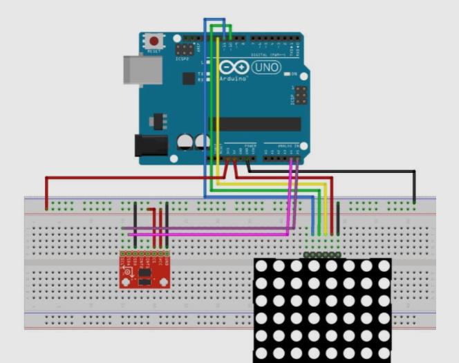
接脚连线:
MAX7219 UNO
VCC →→→→→ 5V
GND →→→→→ GND
DIN →→→→→ D12(数据,数据接收引脚)
CS →→→→→ D11(负载,命令接收引脚)
CLK →→→→→ D10(时钟,时钟引脚)
*/
#include <LedControl.h>
#include <Wire.h>
#define DEVICE (0x53) //ADXL345 device address
#define TO_READ (6) //num of bytes we are going to read (two bytes for each axis)
byte buff[TO_READ] ; //6 bytes buffer for saving data read from the device
char str[512]; //string buffer to transform data before sending it
int MATRIX_WIDTH = 8;
LedControl lc = LedControl(12, 10, 11, 1); // DIN, CLK, CS, NRDEV
unsigned long delaytime = 50;
int x_key = A1;
int y_key = A0;
int x_pos;
int y_pos;
// object that represents a single light location
// future update with gravity
class Grain
{
public:
int x = 0;
int y = 0;
int mass = 1;
};
Grain *g;
void setup()
{
// set up a grain object
g = new Grain();
ClearDisplay();
Wire.begin(); // join i2c bus (address optional for master)
Serial.begin(9600); // start serial for output
//Turning on the ADXL345
writeTo(DEVICE, 0x2D, 0);
writeTo(DEVICE, 0x2D, 16);
writeTo(DEVICE, 0x2D, 8);
}
void loop()
{
// The first axis-acceleration-data register
int regAddress = 0x32;
int x, y, z;
readFrom(DEVICE, regAddress, TO_READ, buff); //read the acceleration data from ADXL345
// Combine the two bytes of each direction
// Least significant bit first
x = (((int)buff[1]) << 8) | buff[0];
y = (((int)buff[3]) << 8) | buff[2];
z = (((int)buff[5]) << 8) | buff[4];
// Convert the values into values that can be represented on the matrix
x = map(x, -300, 300, 0, 8);
y = map(y, -300, 300, 0, 8);
z = map(z, -300, 300, 0, 8);
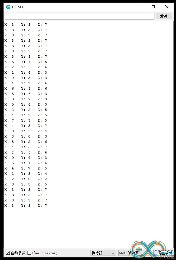
//we send the x y z values as a string to the serial port
Serial.print("X: ");
Serial.print(x);
Serial.print(" Y: ");
Serial.print(y);
Serial.print(" Z: ");
Serial.print(z);
Serial.print("\n");
ClearDisplay();
// assign the grain to this location
g->x = x;
g->y = y;
lc.setLed(0, g->x, g->y, true);
//add some delay between each update
delay(10);
}
void ClearDisplay()
{
// sets up the lcd display
int devices = lc.getDeviceCount();
for (int address = 0; address < devices; address++)
{
lc.shutdown(address, false);
lc.setIntensity(address, 1);
lc.clearDisplay(address);
}
}
//Writes val to address register on device
void writeTo(int device, byte address, byte val)
{
Wire.beginTransmission(device); //start transmission to device
Wire.write(address); // send register address
Wire.write(val); // send value to write
Wire.endTransmission(); //end transmission
}
//reads num bytes starting from address register on device in to buff array
void readFrom(int device, byte address, int num, byte buff[])
{
Wire.beginTransmission(device); //start transmission to device
Wire.write(address); //sends address to read from
Wire.endTransmission(); //end transmission
Wire.beginTransmission(device); //start transmission to device
Wire.requestFrom(device, num); // request 6 bytes from device
int i = 0;
while (Wire.available()) //device may send less than requested (abnormal)
{
buff[i] = Wire.read(); // receive a byte
i++;
}
Wire.endTransmission(); //end transmission
}模块实验接线示意图
实验串口返回情况
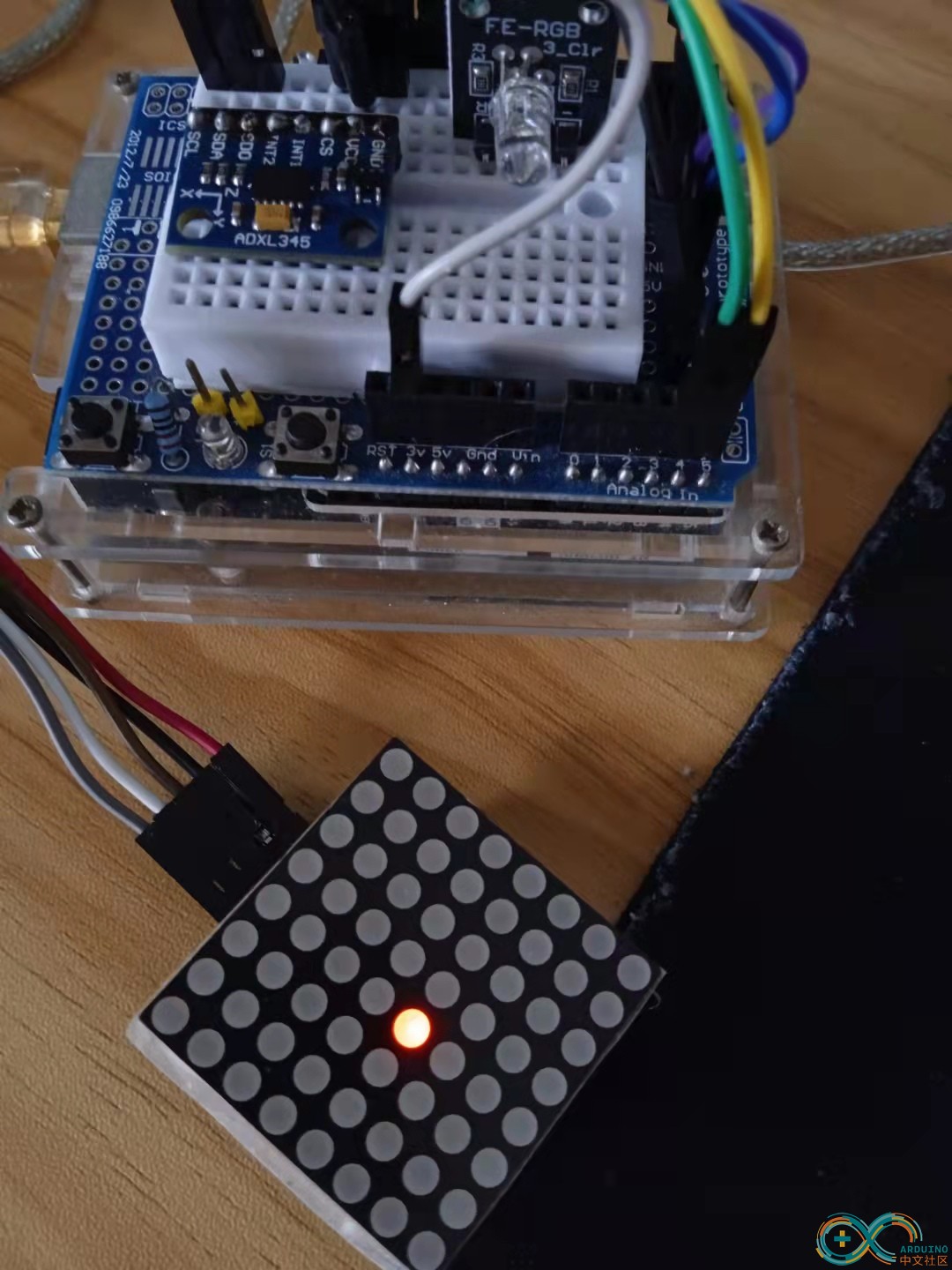
Arduino实验场景图
实验视频剪辑
https://v.youku.com/v_show/id_XNTgxMDI1NTc3Ng==.html?firsttime=0
【Arduino】168种传感器模块系列实验(资料代码+仿真编程+图形编程)
实验二十二:MAX7219点阵显示模块(8X8 LED共阴)
项目三十一:动态音乐频谱仪
实验开源代码
/*
  【Arduino】168种传感器模块系列实验(资料代码+仿真编程+图形编程)
  实验二十二:MAX7219点阵显示模块(8X8 LED共阴)
  项目三十一:动态音乐频谱仪
  接脚连线:
  MAX7219       UNO
  VCC  →→→→→ 5V
  GND  →→→→→ GND
  DIN  →→→→→ D12(数据,数据接收引脚)
  CS   →→→→→ D11(负载,命令接收引脚)
  CLK  →→→→→ D10(时钟,时钟引脚)
*/

#include "LedControl.h"

/* Led matrix - Max7219 Declared */
LedControl lc = LedControl(12, 11, 10, 1);

const int maxScale = 11;

/*  Sensor - Max9812 Declared */
const int sensorPin = A4;
const int sampleWindow = 50;  // 50ms = 20Hz
unsigned int sample;

unsigned long startMillis;
unsigned long timeCycle;

unsigned int signalMax = 0;
unsigned int signalMin = 1024;
unsigned char index = 0;

unsigned int peakToPeak[8];
unsigned int displayPeak[8];
unsigned int temp[8]={0,0,0,0,0,0,0,0};
unsigned int signalMaxBuff[8];
unsigned int signalMinBuff[8];


void setup() {
  // Led matrix
  lc.shutdown(0, false); // bật hiện thị
  lc.setIntensity(0, 1); // chỉnh độ sáng
  lc.clearDisplay(0); // tắt tất cả led

  Serial.begin(9600);
}

void loop() {
  startMillis = millis();
  //peakToPeak = 0;

  signalMax = 0;
  signalMin = 1024;

  // Get data in 50ms
  while (millis() - startMillis < sampleWindow) {
    sample = analogRead(sensorPin);

    if (sample < 1024) {
      if (sample > signalMax) {
        signalMax = sample;
      }
      if (sample < signalMin) {
        signalMin = sample;
      }
    }

    // 20Hz - 64Hz - 125Hz - 250Hz - 500Hz - 1kHz (timeCycle = 1/F)(ms)
    timeCycle = millis() - startMillis;
    if (timeCycle == 1 || timeCycle == 2 || timeCycle == 4 || timeCycle == 8
        || timeCycle == 16 || timeCycle == 32 || timeCycle == 40 || timeCycle == 50) {
              signalMaxBuff[index] = signalMax;
              signalMinBuff[index] = signalMin;
              index = (index + 1) % 8;
              delay(1);
              //Serial.println(timeCycle);
    }
  }

  // Delete pointer to array
  index = 0;

  // Calculation after get samples
  for (int i = 0; i < 8; i++) {  // i = row (led matrix)
    // sound level
    peakToPeak[i] = signalMaxBuff[i] - signalMinBuff[i];

    // Map 1v p-p level to the max scale of the display
    displayPeak[i] = map(peakToPeak[i], 0, 1023, 0, maxScale);

    // Show to led matrix
    displayLed(displayPeak[i], i);

    // Led drop down
    if (displayPeak[i] >= temp[i]) {
      temp[i] = displayPeak[i];
    }
    else {
      temp[i]--;
    }

    lc.setLed(0, i, temp[i], true);
    delayMicroseconds(250);
  }

}

void displayLed(int displayPeak, int row) {
  switch (displayPeak) {
    case 0 : lc.setRow(0, row, 0x80); break;
    case 1 : lc.setRow(0, row, 0xC0); break;
    case 2 : lc.setRow(0, row, 0xE0); break;
    case 3 : lc.setRow(0, row, 0xF0); break;
    case 4 : lc.setRow(0, row, 0xF8); break;
    case 5 : lc.setRow(0, row, 0xFC); break;
    case 6 : lc.setRow(0, row, 0xFE); break;
    case 7 : lc.setRow(0, row, 0xFF); break;
  }
}
【Arduino】168种传感器模块系列实验(资料代码+仿真编程+图形编程)
实验二十二:MAX7219点阵显示模块(8X8 LED共阴)
项目三十一:动态音乐频谱仪
实验视频剪辑
https://v.youku.com/v_show/id_XNTgxMDQ1Mjk4NA==.html?spm=a2hcb.playlsit.page.1
实验场景图 动态图
【Arduino】168种传感器模块系列实验(资料代码+仿真编程+图形编程)
实验二十二:MAX7219点阵显示模块(8X8 LED共阴)
项目三十二:使用 8x8 LED 矩阵和 MAX 模块实现条形图功能
实验开源代码
/*
  【Arduino】168种传感器模块系列实验(资料代码+仿真编程+图形编程)
  实验二十二:MAX7219点阵显示模块(8X8 LED共阴)
  项目三十二:使用 8x8 LED 矩阵和 MAX 模块实现条形图功能
  接脚连线:
  MAX7219       UNO
  VCC  →→→→→ 5V
  GND  →→→→→ GND
  DIN  →→→→→ D12(数据,数据接收引脚)
  CS   →→→→→ D11(负载,命令接收引脚)
  CLK  →→→→→ D10(时钟,时钟引脚)
*/

#include "LedControl.h"

LedControl lc = LedControl(12, 10, 11, 1);

void setup() {
  /*
    MAX72XX 在启动时处于省电模式,
    我们必须叫醒
  */
  lc.shutdown(0, false);
  lc.setIntensity(0, 0); //将亮度设置为0(变暗), 8 是中等
  lc.clearDisplay(0);    //清除显示
}

void loop() {
  int val =  random(0, 9);
  BarScroll(val); //将此值插入条形图中
  delay(100);
}
int bar[8];

void BarScroll(int NewVal) {
  for (int k = 0; k < 7; k++) { //为新的val腾出空间
    bar[k] = bar[k + 1];
  }
  bar[7] = NewVal; //安装新的val
  BarGraph(bar);
}

void BarGraph(int barvals[8]) {
  byte a[9] = {B00000000, B10000000, B11000000, B11100000, B11110000, B11111000, B11111100, B11111110, B11111111};
  for (int k = 0; k < 8; k++) {  //做第k列
    lc.setRow(0, k, a[barvals[k]]); //立即创建列
  }
}


 他的勋章
他的勋章


hacker_2023.07.19
666