 返回首页
返回首页
 回到顶部
回到顶部
37款传感器与执行器的提法,在网络上广泛流传,其实Arduino能够兼容的传感器模块肯定是不止这37种的。鉴于本人手头积累了一些传感器和执行器模块,依照实践出真知(一定要动手做)的理念,以学习和交流为目的,这里准备逐一动手尝试系列实验,不管成功(程序走通)与否,都会记录下来—小小的进步或是搞不掂的问题,希望能够抛砖引玉。
【Arduino】168种传感器模块系列实验(资料代码+仿真编程+图形编程)
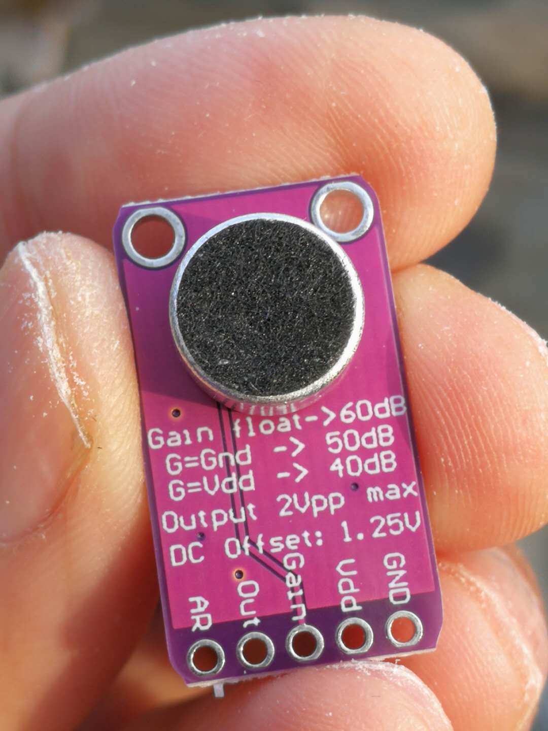
实验一百四十九:MAX9814麦克风放大器模块 MIC话筒声音放大/咪头传感器
【Arduino】168种传感器模块系列实验(资料代码+仿真编程+图形编程)
实验一百四十九:MAX9814麦克风放大器模块 MIC话筒声音放大/咪头传感器
项目测试:测量噪音水平(以dB为单位)
Arduino实验开源代码
/*
【Arduino】168种传感器模块系列实验(资料代码+仿真编程+图形编程)
实验一百四十九:MAX9814麦克风放大器模块 MIC话筒声音放大/咪头传感器
项目测试:测量噪音水平(以dB为单位)
模块接线:
MAX9814 Arduino
VCC 5V
GND GND
OUT A0
*/
const int MIC = 0; //MAX9814麦克风放大器输出连接到引脚 A0
int adc;
int dB, PdB; //将保存每次从麦克风读取的值的变量
void setup() {
Serial.begin(9600); //将波特率设置为 9600,以便我们可以检查麦克风在串行监视器上获得的值
pinMode(13, OUTPUT); //LED灯接入D13脚,并设置为输出
}
void loop() {
PdB = dB; //在此处存储 dB 的前一个
adc = analogRead(MIC); //从放大器读取 ADC 值
//Serial.println (adc);//打印 ADC 用于初始计算
dB = (adc + 83.2073) / 11.003; //使用回归值将 ADC 值转换为 dB
if (PdB != dB)
Serial.print ("dB ");
Serial.println (dB);
if (dB > 50) //当dB值大于50时,点亮LED灯
{
digitalWrite(13, HIGH); // 打开 LED(HIGH 是电压电平)
delay(500); // 等一下,延时500毫秒
digitalWrite(13, LOW);
}
delay(100);
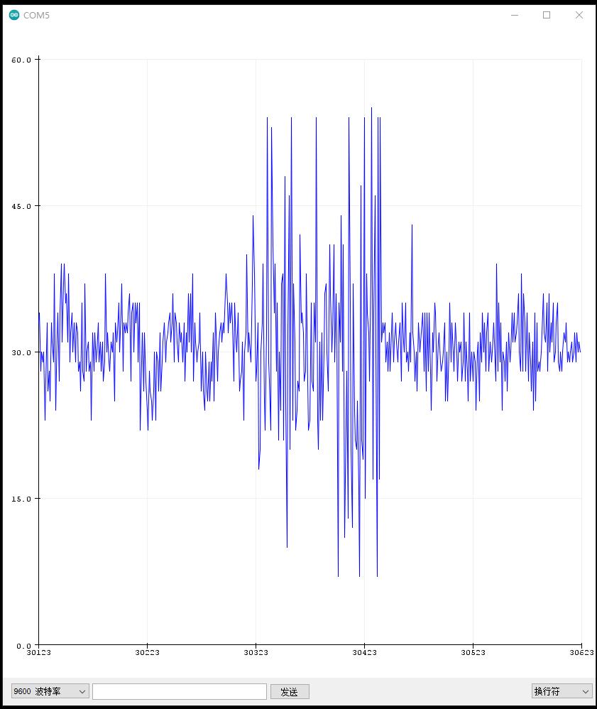
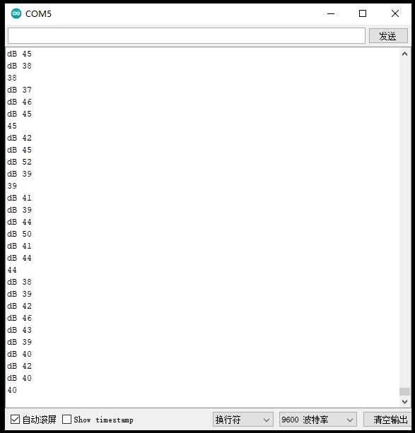
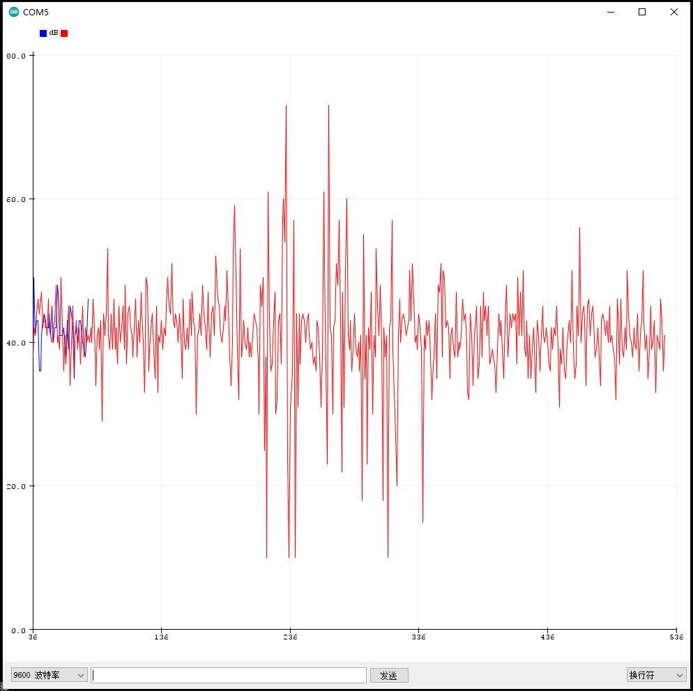
}实验串口绘图器返回情况截图
注意:项目的目的不是准确测量dB,而是仅提供尽可能接近实际值的值。
实验串口绘图器返回情况截图之二
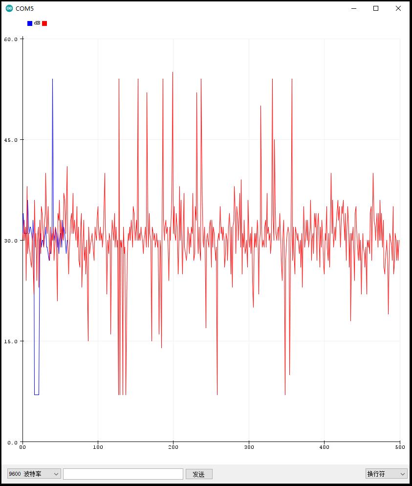
项目测试:测量噪音水平(以dB为单位)
实验场景图
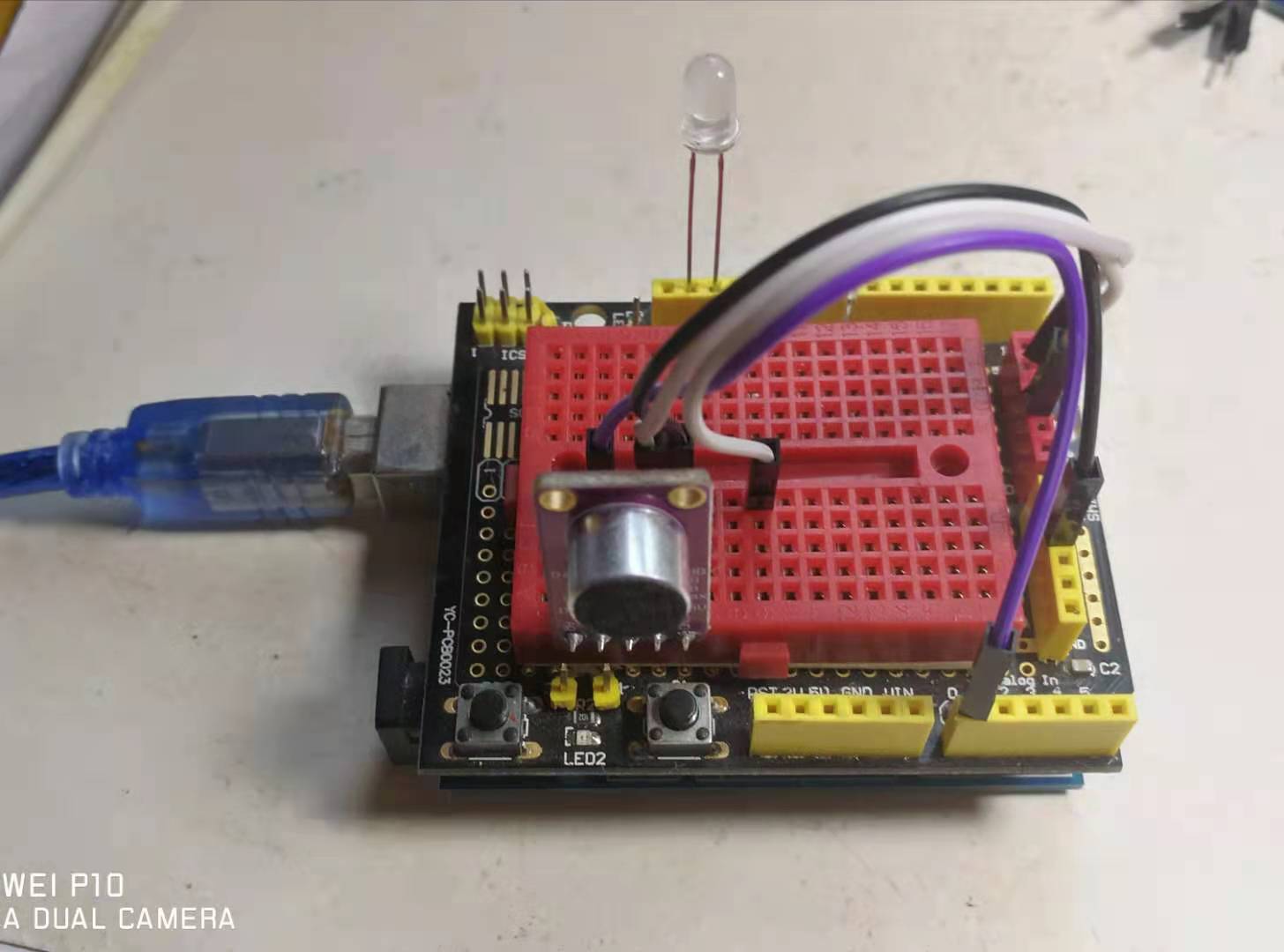
项目实验:简易测量环境的噪音水平(以dB为单位)
https://v.youku.com/v_show/id_XNTE2OTc3MzI1Mg==.html?spm=a2hcb.playlsit.page.1 (实验视频36秒)
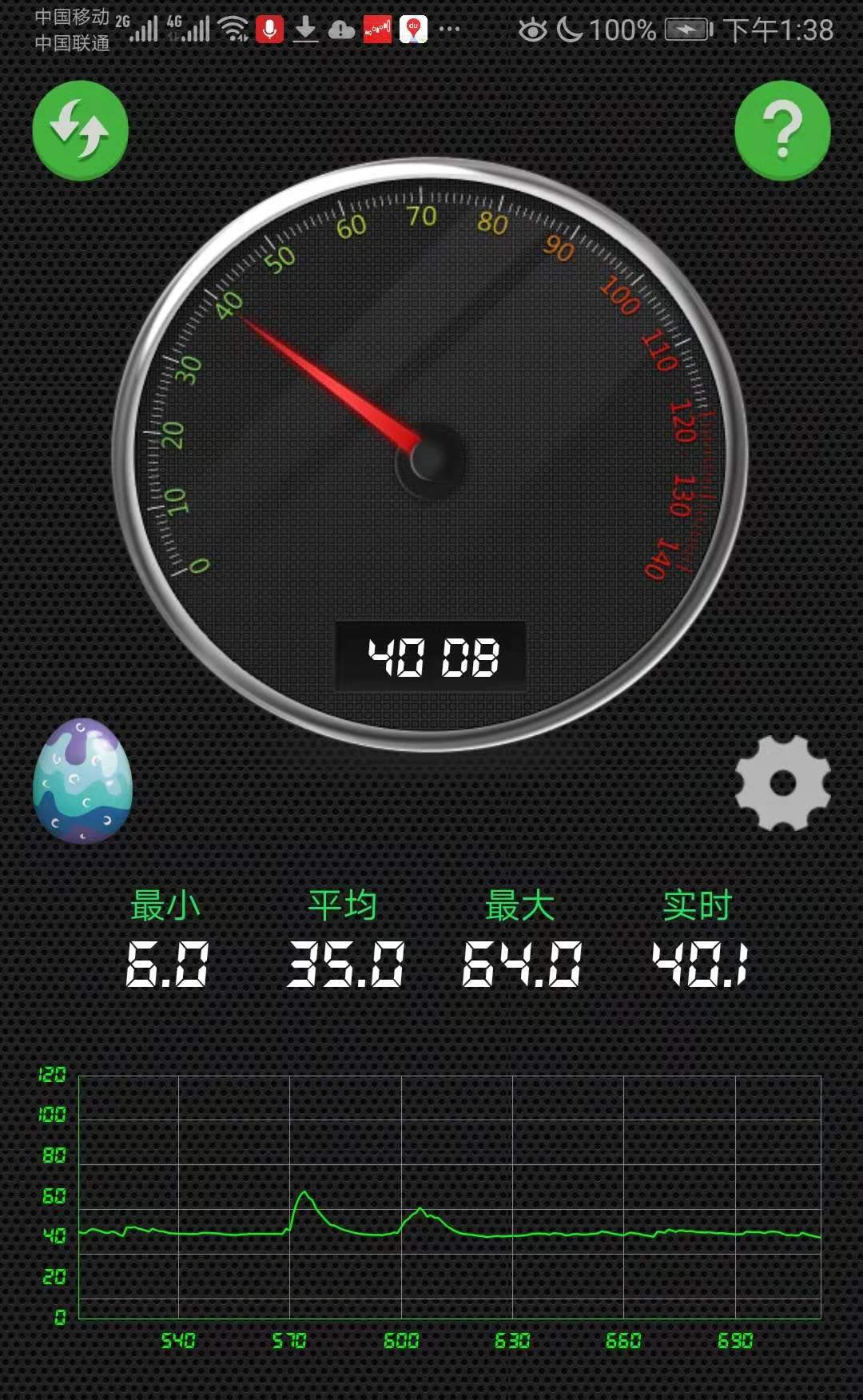
简单校对,在手机应用宝上搜索——分贝噪声仪,安装1-2款APP
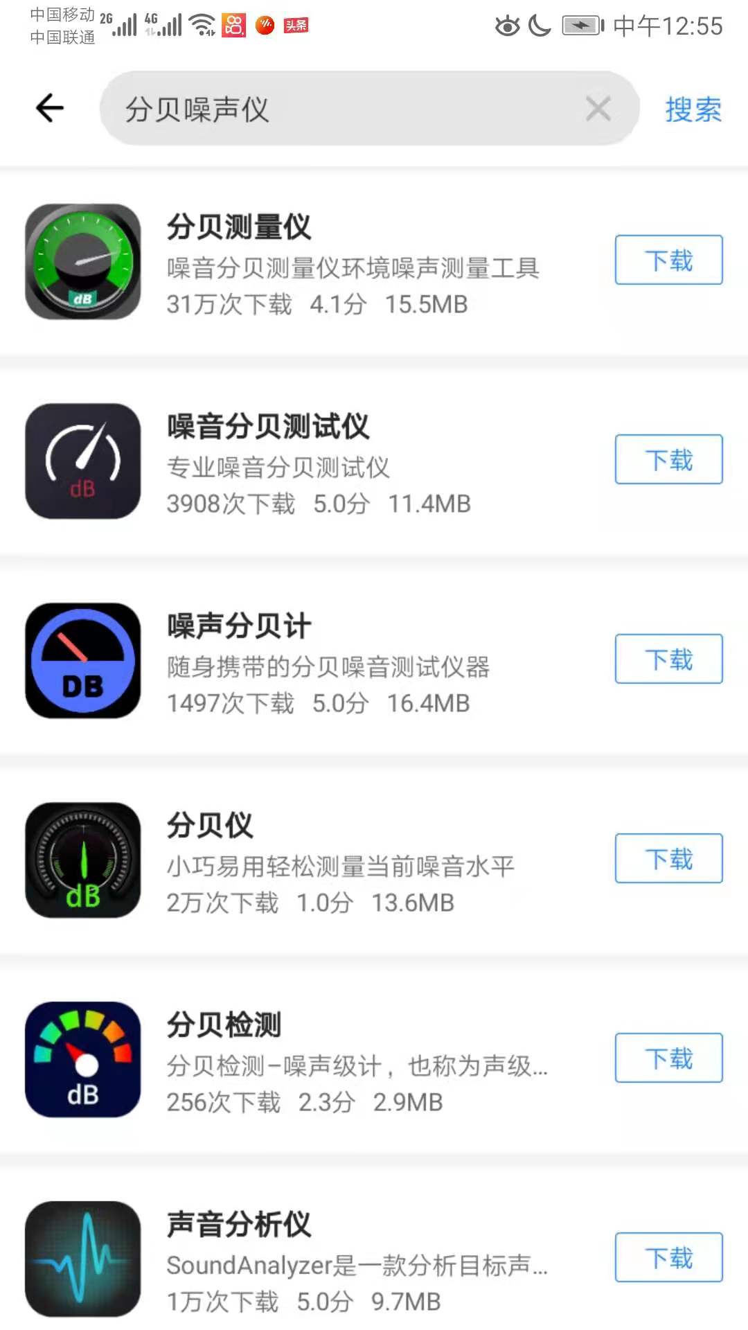
下载安装了《分贝噪声测试》
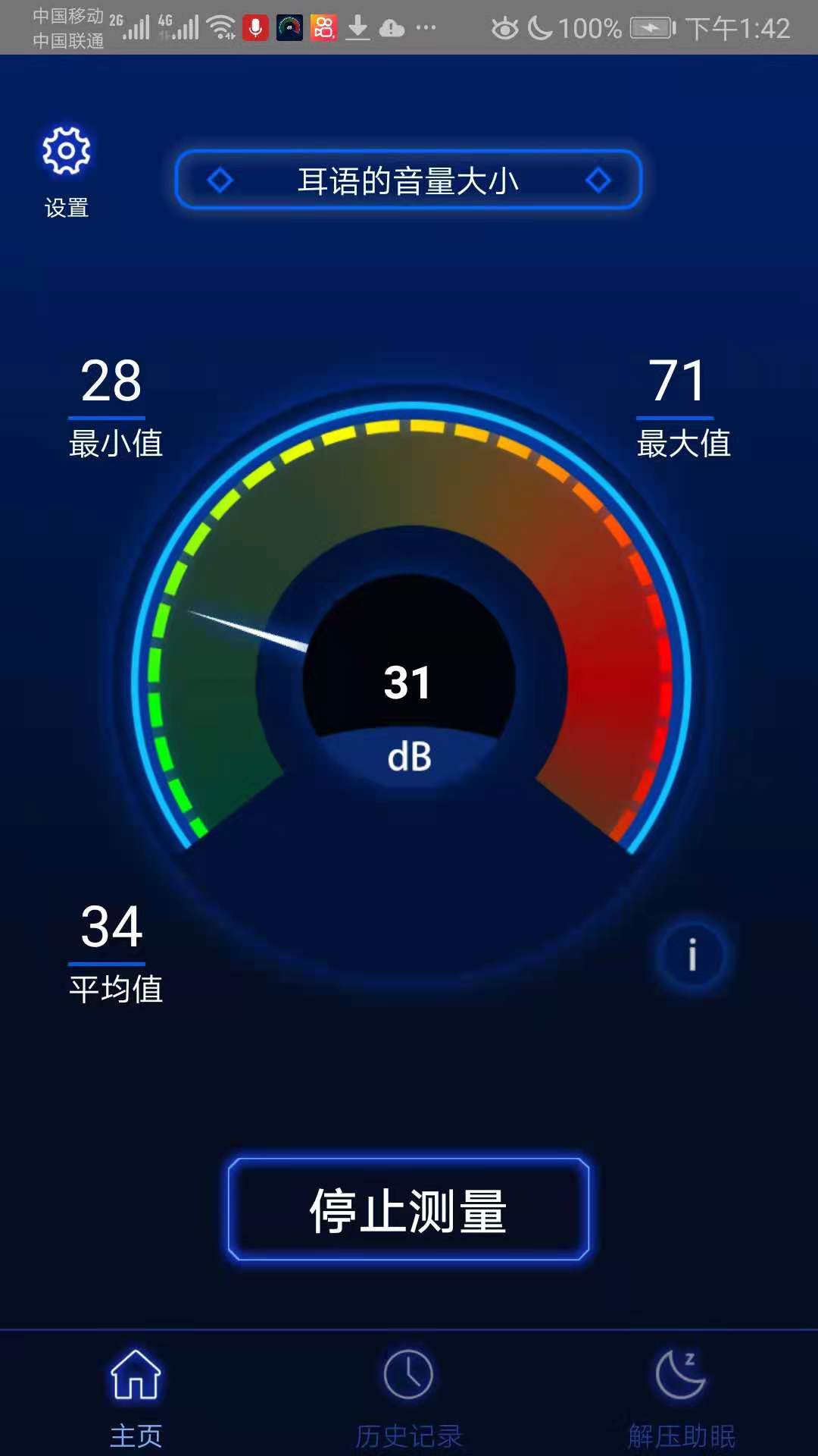
还有《分贝测量仪》
校正后实验程序
/*

【Arduino】168种传感器模块系列实验(资料代码+仿真编程+图形编程)

  实验一百四十九:MAX9814麦克风放大器模块 MIC话筒声音放大/咪头传感器

 项目测试:测量噪音水平(以dB为单位)

 模块接线:

 MAX9814 Arduino

 VCC    5V

 GND    GND

 OUT     A0

*/

const int MIC = 0; //MAX9814麦克风放大器输出连接到引脚 A0

int adc;

int dB, PdB; //将保存每次从麦克风读取的值的变量

void setup() {

 Serial.begin(9600); //将波特率设置为 9600,以便我们可以检查麦克风在串行监视器上获得的值

 pinMode(13, OUTPUT); //LED灯接入D13脚,并设置为输出

}

void loop() {

 PdB = dB; //在此处存储 dB 的前一个

 adc = analogRead(MIC); //从放大器读取 ADC 值

 //Serial.println (adc);//打印 ADC 用于初始计算

 dB = (adc + 83.2073) / 8.083; //使用回归值将 ADC 值转换为 dB

 if (PdB != dB)

  Serial.print ("dB ");

  Serial.println (dB);

 if (dB > 55) //当dB值大于55时,点亮LED灯

 {

  digitalWrite(13, HIGH);  // 打开 LED(HIGH 是电压电平)

  delay(500);        // 等一下,延时500毫秒

  digitalWrite(13, LOW);

 }

 delay(100);

}
实验串口输出情况
实验串口绘图器绘图输出
【Arduino】168种传感器模块系列实验(资料代码+仿真编程+图形编程)
实验一百四十九:MAX9814麦克风放大器模块 MIC话筒声音放大/咪头传感器
项目之九:Arduino 的小型音频可视化
Arduino实验开源代码
/*

【Arduino】168种传感器模块系列实验(资料代码+仿真编程+图形编程)

  实验一百四十九:MAX9814麦克风放大器模块 MIC话筒声音放大/咪头传感器

 项目之九:Arduino 的小型音频可视化

 模块接线:

 - 3.3V 至麦克风放大器 + 和 Arduino AREF 引脚 <-- 重要!

 MAX9814 Arduino

 VCC    3.3V

 GND    GND

 OUT     A0

 VK16k33  UNO

 VIN    5V

 GND    GND

 SCL    A5

 SDA    A4

*/

// 重要提示:FFT_N 应该在 ffft.h 中 #defined 为 128。

#include <avr/pgmspace.h>

#include <ffft.h>

#include <math.h>

#include <Wire.h>

#include <Adafruit_GFX.h>

#include <Adafruit_LEDBackpack.h>

// Microphone connects to Analog Pin 0. Corresponding ADC channel number

// varies among boards...it's ADC0 on Uno and Mega, ADC7 on Leonardo.

// Other boards may require different settings; refer to datasheet.

#ifdef __AVR_ATmega32U4__

#define ADC_CHANNEL 7

#else

#define ADC_CHANNEL 0

#endif

int16_t    capture[FFT_N];  // Audio capture buffer

complex_t   bfly_buff[FFT_N]; // FFT "butterfly" buffer

uint16_t   spectrum[FFT_N / 2]; // Spectrum output buffer

volatile byte samplePos = 0;   // Buffer position counter

byte

peak[8],   // Peak level of each column; used for falling dots

   dotCount = 0, // Frame counter for delaying dot-falling speed

   colCount = 0; // Frame counter for storing past column data

int

col[8][10],  // Column levels for the prior 10 frames

  minLvlAvg[8], // For dynamic adjustment of low & high ends of graph,

  maxLvlAvg[8], // pseudo rolling averages for the prior few frames.

  colDiv[8];  // Used when filtering FFT output to 8 columns

/*

 These tables were arrived at through testing, modeling and trial and error,

 exposing the unit to assorted music and sounds. But there's no One Perfect

 EQ Setting to Rule Them All, and the graph may respond better to some

 inputs than others. The software works at making the graph interesting,

 but some columns will always be less lively than others, especially

 comparing live speech against ambient music of varying genres.

*/

static const uint8_t PROGMEM

// This is low-level noise that's subtracted from each FFT output column:

noise[64] = { 8, 6, 6, 5, 3, 4, 4, 4, 3, 4, 4, 3, 2, 3, 3, 4,

       2, 1, 2, 1, 3, 2, 3, 2, 1, 2, 3, 1, 2, 3, 4, 4,

       3, 2, 2, 2, 2, 2, 2, 1, 3, 2, 2, 2, 2, 2, 2, 2,

       2, 2, 2, 2, 2, 2, 2, 2, 2, 2, 2, 2, 2, 3, 3, 4

      },

      // These are scaling quotients for each FFT output column, sort of a

      // graphic EQ in reverse. Most music is pretty heavy at the bass end.

eq[64] = {

 255, 175, 218, 225, 220, 198, 147, 99, 68, 47, 33, 22, 14, 8, 4, 2,

 0,  0, 0, 0, 0, 0, 0, 0, 0, 0, 0, 0, 0, 0, 0, 0,

 0,  0, 0, 0, 0, 0, 0, 0, 0, 0, 0, 0, 0, 0, 0, 0,

 0,  0, 0, 0, 0, 0, 0, 0, 0, 0, 0, 0, 0, 0, 0, 0

},

// When filtering down to 8 columns, these tables contain indexes

// and weightings of the FFT spectrum output values to use. Not all

// buckets are used -- the bottom-most and several at the top are

// either noisy or out of range or generally not good for a graph.

col0data[] = { 2, 1, // # of spectrum bins to merge, index of first

        111,  8

       },      // Weights for each bin

       col1data[] = { 4, 1, // 4 bins, starting at index 1

               19, 186, 38,  2

             }, // Weights for 4 bins. Got it now?

             col2data[] = { 5, 2,

                     11, 156, 118, 16,  1

                    },

                    col3data[] = { 8, 3,

                            5, 55, 165, 164, 71, 18,  4,  1

                          },

                      col4data[] = { 11, 5,

                             3, 24, 89, 169, 178, 118, 54, 20,  6,  2,  1

                            },

                        col5data[] = { 17, 7,

                               2,  9, 29, 70, 125, 172, 185, 162, 118, 74,

                               41, 21, 10,  5,  2,  1,  1

                              },

                          col6data[] = { 25, 11,

                                 1,  4, 11, 25, 49, 83, 121, 156, 180, 185,

                                 174, 149, 118, 87, 60, 40, 25, 16, 10,  6,

                                 4,  2,  1,  1,  1

                                },

                            col7data[] = { 37, 16,

                                   1,  2,  5, 10, 18, 30, 46, 67, 92, 118,

                                   143, 164, 179, 185, 184, 174, 158, 139, 118, 97,

                                   77, 60, 45, 34, 25, 18, 13,  9,  7,  5,

                                   3,  2,  2,  1,  1,  1,  1

                                  },

                              // And then this points to the start of the data for each of the columns:

* const colData[] = {

 col0data, col1data, col2data, col3data,

 col4data, col5data, col6data, col7data

};

Adafruit_BicolorMatrix matrix = Adafruit_BicolorMatrix();

void setup() {

 uint8_t i, j, nBins, binNum, *data;

 memset(peak, 0, sizeof(peak));

 memset(col , 0, sizeof(col));

 for (i = 0; i < 8; i++) {

  minLvlAvg[i] = 0;

  maxLvlAvg[i] = 512;

  data     = (uint8_t *)pgm_read_word(&colData[i]);

  nBins    = pgm_read_byte(&data[0]) + 2;

  binNum    = pgm_read_byte(&data[1]);

  for (colDiv[i] = 0, j = 2; j < nBins; j++)

   colDiv[i] += pgm_read_byte(&data[j]);

 }

 matrix.begin(0x70);

 // Init ADC free-run mode; f = ( 16MHz/prescaler ) / 13 cycles/conversion

 ADMUX = ADC_CHANNEL; // Channel sel, right-adj, use AREF pin

 ADCSRA = _BV(ADEN) | // ADC enable

      _BV(ADSC) | // ADC start

      _BV(ADATE) | // Auto trigger

      _BV(ADIE) | // Interrupt enable

      _BV(ADPS2) | _BV(ADPS1) | _BV(ADPS0); // 128:1 / 13 = 9615 Hz

 ADCSRB = 0;        // Free run mode, no high MUX bit

 DIDR0 = 1 << ADC_CHANNEL; // Turn off digital input for ADC pin

 TIMSK0 = 0;        // Timer0 off

 sei(); // Enable interrupts

}

void loop() {

 uint8_t i, x, L, *data, nBins, binNum, weighting, c;

 uint16_t minLvl, maxLvl;

 int   level, y, sum;

 while (ADCSRA & _BV(ADIE)); // Wait for audio sampling to finish

 fft_input(capture, bfly_buff);  // Samples -> complex #s

 samplePos = 0;          // Reset sample counter

 ADCSRA |= _BV(ADIE);       // Resume sampling interrupt

 fft_execute(bfly_buff);     // Process complex data

 fft_output(bfly_buff, spectrum); // Complex -> spectrum

 // Remove noise and apply EQ levels

 for (x = 0; x < FFT_N / 2; x++) {

  L = pgm_read_byte(&noise[x]);

  spectrum[x] = (spectrum[x] <= L) ? 0 :

         (((spectrum[x] - L) * (256L - pgm_read_byte(&eq[x]))) >> 8);

 }

 // Fill background w/colors, then idle parts of columns will erase

 matrix.fillRect(0, 0, 8, 3, LED_RED);  // Upper section

 matrix.fillRect(0, 3, 8, 2, LED_YELLOW); // Mid

 matrix.fillRect(0, 5, 8, 3, LED_GREEN); // Lower section

 // Downsample spectrum output to 8 columns:

 for (x = 0; x < 8; x++) {

  data  = (uint8_t *)pgm_read_word(&colData[x]);

  nBins = pgm_read_byte(&data[0]) + 2;

  binNum = pgm_read_byte(&data[1]);

  for (sum = 0, i = 2; i < nBins; i++)

   sum += spectrum[binNum++] * pgm_read_byte(&data[i]); // Weighted

  col[x][colCount] = sum / colDiv[x];          // Average

  minLvl = maxLvl = col[x][0];

  for (i = 1; i < 10; i++) { // Get range of prior 10 frames

   if (col[x][i] < minLvl)   minLvl = col[x][i];

   else if (col[x][i] > maxLvl) maxLvl = col[x][i];

  }

  // minLvl and maxLvl indicate the extents of the FFT output, used

  // for vertically scaling the output graph (so it looks interesting

  // regardless of volume level). If they're too close together though

  // (e.g. at very low volume levels) the graph becomes super coarse

  // and 'jumpy'...so keep some minimum distance between them (this

  // also lets the graph go to zero when no sound is playing):

  if ((maxLvl - minLvl) < 8) maxLvl = minLvl + 8;

  minLvlAvg[x] = (minLvlAvg[x] * 7 + minLvl) >> 3; // Dampen min/max levels

  maxLvlAvg[x] = (maxLvlAvg[x] * 7 + maxLvl) >> 3; // (fake rolling average)

  // Second fixed-point scale based on dynamic min/max levels:

  level = 10L * (col[x][colCount] - minLvlAvg[x]) /

      (long)(maxLvlAvg[x] - minLvlAvg[x]);

  // Clip output and convert to byte:

  if (level < 0L)   c = 0;

  else if (level > 10) c = 10; // Allow dot to go a couple pixels off top

  else        c = (uint8_t)level;

  if (c > peak[x]) peak[x] = c; // Keep dot on top

  if (peak[x] <= 0) { // Empty column?

   matrix.drawLine(x, 0, x, 7, LED_OFF);

   continue;

  } else if (c < 8) { // Partial column?

   matrix.drawLine(x, 0, x, 7 - c, LED_OFF);

  }

  // The 'peak' dot color varies, but doesn't necessarily match

  // the three screen regions...yellow has a little extra influence.

  y = 8 - peak[x];

  if (y < 2)   matrix.drawPixel(x, y, LED_RED);

  else if (y < 6) matrix.drawPixel(x, y, LED_YELLOW);

  else      matrix.drawPixel(x, y, LED_GREEN);

 }

 matrix.writeDisplay();

 // Every third frame, make the peak pixels drop by 1:

 if (++dotCount >= 3) {

  dotCount = 0;

  for (x = 0; x < 8; x++) {

   if (peak[x] > 0) peak[x]--;

  }

 }

 if (++colCount >= 10) colCount = 0;

}

ISR(ADC_vect) { // Audio-sampling interrupt

 static const int16_t noiseThreshold = 4;

 int16_t       sample     = ADC; // 0-1023

 capture[samplePos] =

  ((sample > (512 - noiseThreshold)) &&

   (sample < (512 + noiseThreshold))) ? 0 :

  sample - 512; // Sign-convert for FFT; -512 to +511

 if (++samplePos >= FFT_N) ADCSRA &= ~_BV(ADIE); // Buffer full, interrupt off

}
实验场景图 动态图
项目之九:Arduino 的小型音频可视化 (49秒视频)
https://v.youku.com/v_show/id_XNTgwNTE5NTU0OA==.html?spm=a2hcb.playlsit.page.1
【Arduino】168种传感器模块系列实验(资料代码+仿真编程+图形编程)
实验一百四十九:MAX9814麦克风放大器模块 MIC话筒声音放大/咪头传感器
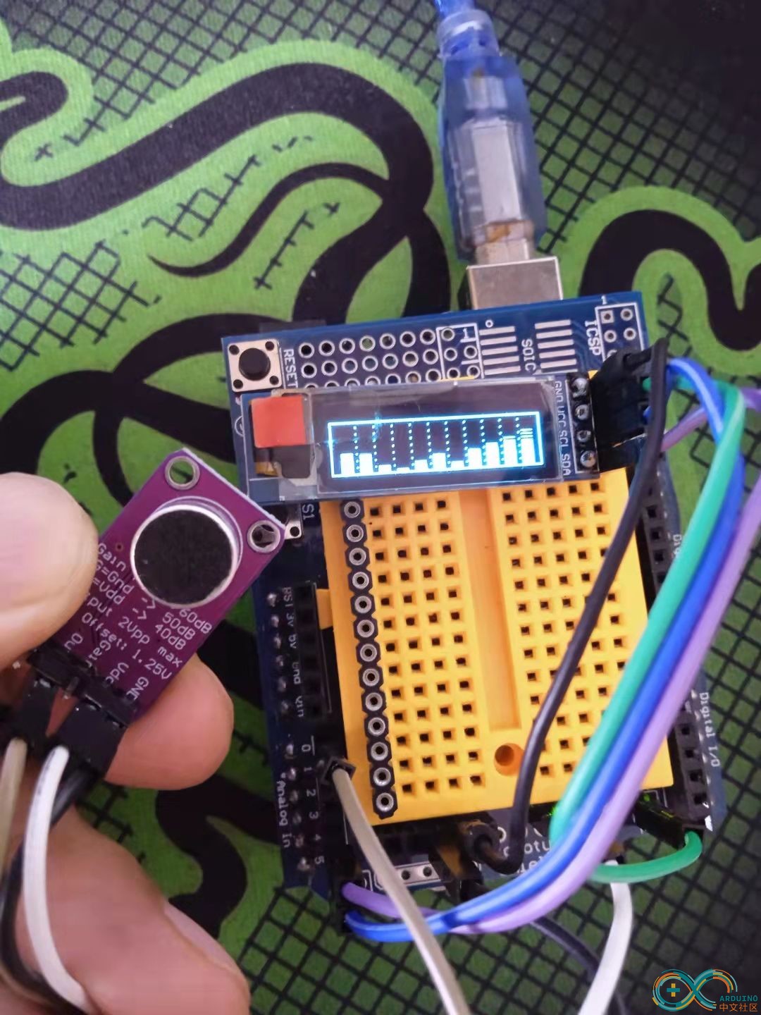
项目十六:使用FFT库的迷你音乐频谱仪(声谱可视化器)
实验接线方法: max9814接A0
oled模块 Ardunio Uno
GND---------GND接地线
VCC---------5V 接电源
SDA---------A4
SCL ------- A5
/*

【Arduino】168种传感器模块系列实验(资料代码+仿真编程+图形编程)

  实验一百四十九:MAX9814麦克风放大器模块 MIC话筒声音放大/咪头传感器

 项目十六:使用FFT库的迷你音乐频谱仪(声谱可视化器)

 实验接线方法: max9814接A0

 oled模块  Ardunio Uno

 GND---------GND接地线

 VCC---------5V 接电源

 SDA---------A4

 SCL ------- A5

*/

#include "arduinoFFT.h"

#include <Adafruit_GFX.h>

#include <Adafruit_SSD1306.h>

#define SAMPLES 64 // power of 2

#define SAMPLING_FREQ 8000 // 12 kHz Fmax = sampleF /2

#define AMPLITUDE 100 // 灵敏度

#define FREQUENCY_BANDS 14

#define SCREEN_WIDTH 128

#define SCREEN_HEIGHT 32

#define BARWIDTH 11

#define BARS 11

#define ANALOG_PIN A0

#define OLED_RESET   -1 // 重置引脚 #(如果共享 Arduino 重置引脚,则为 -1)

Adafruit_SSD1306 display(SCREEN_WIDTH, SCREEN_HEIGHT, &Wire, OLED_RESET);

double vImag[SAMPLES];

double vReal[SAMPLES];

unsigned long sampling_period_us;

arduinoFFT fft = arduinoFFT(vReal, vImag, SAMPLES, SAMPLING_FREQ);

//调整参考以去除背景噪声

float reference = log10(60.0);

double coutoffFrequencies[FREQUENCY_BANDS];

void setup() {

 // SSD1306_SWITCHCAPVCC = generate display voltage from 3.3V internally

 if (!display.begin(SSD1306_SWITCHCAPVCC, 0x3C)) { // Address 0x3C for 128x32

  for (;;); // Don't proceed, loop forever

 }

 // Setup display

 display.clearDisplay();

 display.display();

 display.setRotation(0);

 display.invertDisplay(false);

 sampling_period_us = (1.0 / SAMPLING_FREQ ) * pow(10.0, 6);

 // 计算截止频率,以对数标度为基数 POt

 double basePot = pow(SAMPLING_FREQ / 2.0, 1.0 / FREQUENCY_BANDS);

 coutoffFrequencies[0] = basePot;

 for (int i = 1 ; i < FREQUENCY_BANDS; i++ ) {

  coutoffFrequencies[i] = basePot * coutoffFrequencies[i - 1];

 }

 // 绘制虚线以分离频段

 for (int i = 0; i < BARS - 1 ; i++) {

  for (int j = 0; j < SCREEN_HEIGHT ; j += 4) {

   display.writePixel((i + 1)*BARWIDTH + 2 , j, SSD1306_WHITE );

  }

 }

 display.drawRect(0, 0, SCREEN_WIDTH, SCREEN_HEIGHT, SSD1306_WHITE);

}

int oldHeight[20];

int oldMax[20];

double maxInFreq;

void loop() {

 // 采样

 for (int i = 0; i < SAMPLES; i++) {

  unsigned long newTime = micros();

  int value = analogRead(ANALOG_PIN);

  vReal[i] = value;

  vImag[i] = 0;

  while (micros() < (newTime + sampling_period_us)) {

   yield();

  }

 }

 // 计算 FFT

 fft.DCRemoval();

 fft.Windowing(FFT_WIN_TYP_HAMMING, FFT_FORWARD);

 fft.Compute(FFT_FORWARD);

 fft.ComplexToMagnitude();

 double median[20];

 double max[20];

 int index = 0;

 double hzPerSample = (1.0 * SAMPLING_FREQ) / SAMPLES; //

 double hz = 0;

 double maxinband = 0;

 double sum = 0;

 int count = 0;

 for (int i = 2; i < (SAMPLES / 2) ; i++) {

  count++;

  sum += vReal[i];

  if (vReal[i] > max[index] ) {

   max[index] = vReal[i];

  }

  if (hz > coutoffFrequencies[index]) {

   median[index] = sum / count;

   sum = 0.0;

   count = 0;

   index++;

   max[index] = 0;

   median[index] = 0;

  }

  hz += hzPerSample;

 }

 // 计算每个频段的中值和最大值

 if ( sum > 0.0) {

  median[index] = sum / count;

  if (median[index] > maxinband) {

   maxinband = median[index];

  }

 }

 int bar = 0;

 for (int i = FREQUENCY_BANDS - 1; i >= 3; i--) {

  int newHeight = 0;

  int newMax = 0;

  // 计算实际分贝

  if (median[i] > 0 && max[i] > 0 ) {

   newHeight = 20.0 * (log10(median[i] ) - reference);

   newMax = 20.0 * (log10(max[i] ) - reference);

  }

  // 调整最小和最大级别

  if (newHeight < 0 || newMax < 0) {

   newHeight = 1;

   newMax = 1;

  }

  if (newHeight >= SCREEN_HEIGHT - 2) {

   newHeight = SCREEN_HEIGHT - 3;

  }

  if (newMax >= SCREEN_HEIGHT - 2) {

   newMax = SCREEN_HEIGHT - 3;

  }

  int barX = bar * BARWIDTH + 5;

  // 删除旧水平中位数

  if (oldHeight[i] > newHeight) {

   display.fillRect(barX, newHeight + 1, 7, oldHeight[i], SSD1306_BLACK);

  }

  // 删除旧的最大级别

  if ( oldMax[i] > newHeight) {

   for (int j = oldMax[i]; j > newHeight; j -= 2) {

    display.drawFastHLine(barX , j, 7, SSD1306_BLACK);

   }

  }

  // 绘制新的最大级别

  for (int j = newMax; j > newHeight; j -= 2) {

   display.drawFastHLine(barX , j, 7, SSD1306_WHITE);

  }

  // 绘制新的级别中位数

  display.fillRect(barX , 1, 7, newHeight, SSD1306_WHITE);

  oldMax[i] = newMax;

  oldHeight[i] = newHeight;

  bar++;

 }

 display.drawFastHLine(0 , SCREEN_HEIGHT - 1, SCREEN_WIDTH, SSD1306_WHITE);

 display.display();

}
实验场景图
项目十六:使用FFT库的迷你音乐频谱仪(声谱可视化器)(视频67秒)
https://v.youku.com/v_show/id_XNTgwNzU4NDQwOA==.html?spm=a2hcb.playlsit.page.1
项目十六:使用FFT库的迷你音乐频谱仪(声谱可视化器)(测试视频113秒)
https://v.youku.com/v_show/id_XNTgwNzYwODA2OA==.html?spm=a2hcb.playlsit.page.1


 他的勋章
他的勋章


hacker_2023.08.15
666