 返回首页
返回首页
 回到顶部
回到顶部

步骤1 概述
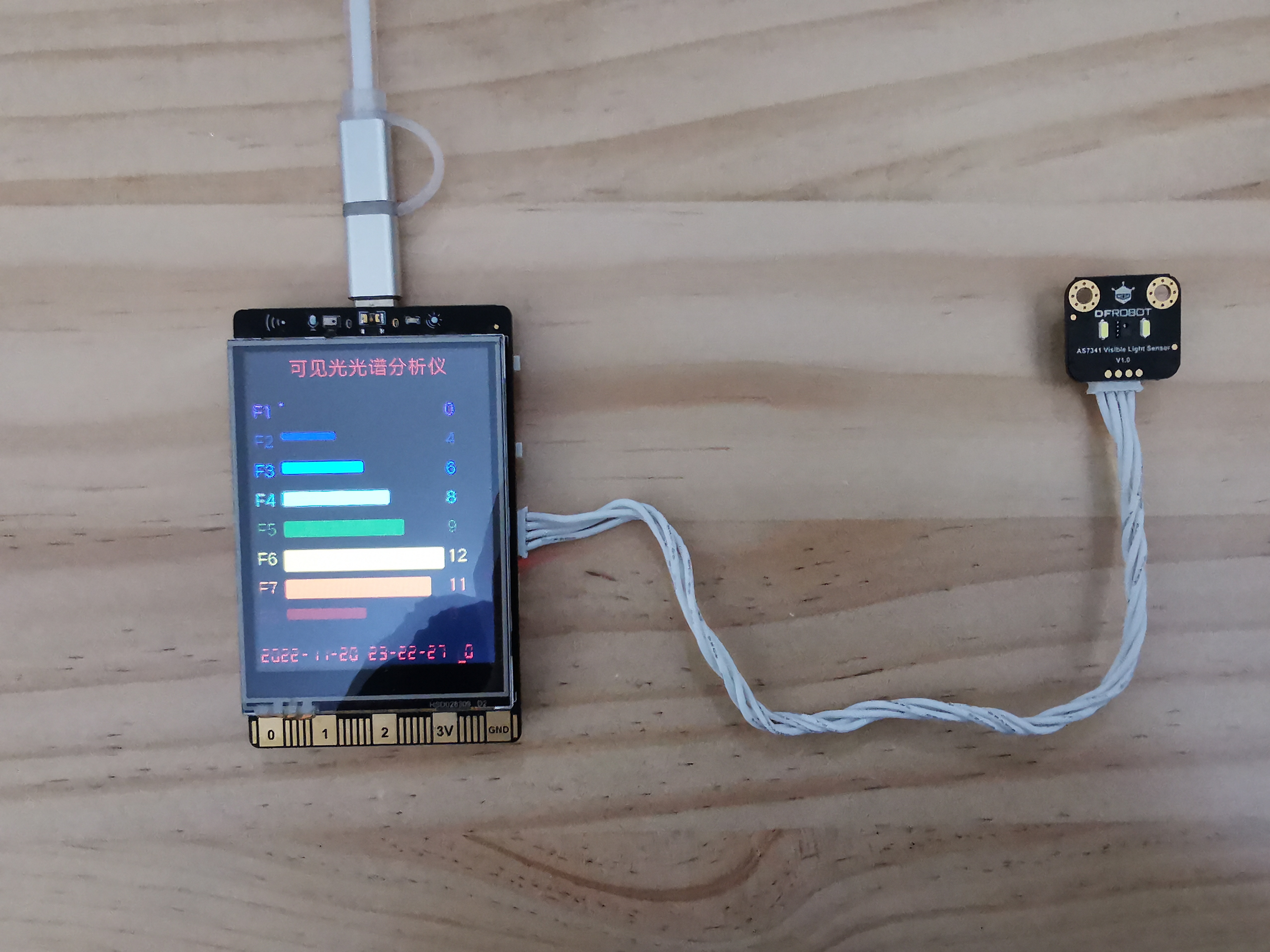
行空板自带屏幕,虽然分辨率不是很高,只有320*240,但是现实还是不错的,而且操作也比较的方便。结合AS7341可见光传感器,可以很方便的分析可见光的光谱信息,并在屏幕上进行呈现,从而成为一款可见光光谱分析仪。
步骤2 硬件材料
材料清单
- 行空板 X1 链接
材料清单
- AS7341可见光谱传感器 X1 链接
材料清单
- https://www.dfrobot.com.cn/goods-3618.html X1 链接
材料清单
- https://www.dfrobot.com.cn/goods-2843.html X1 链接
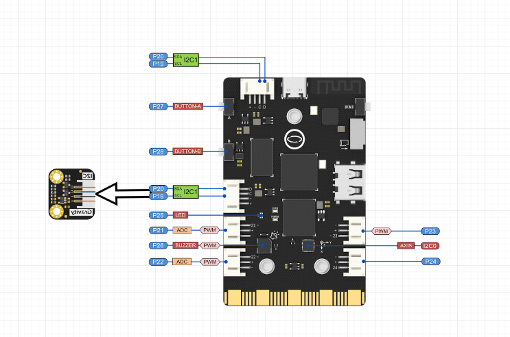
步骤3 原理图
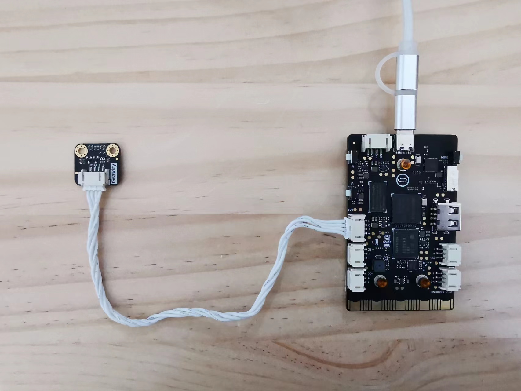
步骤4 实物连线
步骤5 逻辑设计

步骤6 代码编写
# -*- coding:utf-8 -*-
import time
from pinpong.board import Board
from pinpong.libs.dfrobot_as7341 import AS7341
from PIL import Image, ImageDraw
from unihiker import GUI


# 设定颜色区块信息
x0 = 50
y0 = 220
wh = 90
lwh = 34

# 设定屏幕宽高
W = 240
H = 320

# 初始化板子
Board("UNIHIKER").begin()

# 实例化GUI对象
gui=GUI()

# 打开AS7341 FLICKER图片
flicker_image = Image.open("AS7341_Flicker.jpg")

# 设定F1-F8的顺序
colors_where = dict()
colors_where['F1'] = (0,0)
colors_where['F2'] = (2,1)
colors_where['F3'] = (1,0)
colors_where['F4'] = (3,1)
colors_where['F5'] = (2,0)
colors_where['F6'] = (0,1)
colors_where['F7'] = (3,0)
colors_where['F8'] = (1,1)

# 预设定颜色
colors = dict()

# 显示图片
flicker_image_obj = gui.draw_image(x=0, y=0, w=160, h=160, image=flicker_image)

# 获取背景颜色
bgc = flicker_image.getpixel((10, 100))

# 创建新的图像,用于显示获取的颜色值
tile_img = Image.new('RGB', flicker_image.size, bgc)

# 在新图像上,创建画板
tile_img1 = ImageDraw.Draw(tile_img)

# 按位置复刻颜色区块
if False:
    for i in range(0,4):
        for j in range(0,4):
            # 计算坐标
            x = x0 + i * (wh+lwh)
            y = y0 + j * (wh+lwh)

            # 获取颜色
            c = flicker_image.getpixel((x+10, y+10))

            # 设置要显示的区块大小
            shape = [(x, y), (x+wh, y+wh)]

            # 绘制区块
            tile_img1.rectangle(shape, fill =c, outline =c)

# 获取各颜色区块的颜色值,并复刻区块
if True:
    for f in colors_where:
        # 获取顺序值
        i = colors_where[f][0]
        j = colors_where[f][1]

        # 计算坐标
        x = x0 + i * (wh+lwh)
        y = y0 + j * (wh+lwh)

        # 获取颜色
        c = flicker_image.getpixel((x+10, y+10))

        # 设置要显示的区块大小
        shape = [(x, y), (x+wh, y+wh)]

        # 绘制区块
        tile_img1.rectangle(shape, fill =c, outline =c)

        # 记录F1-F8对应的颜色值
        colors[f] = c

# 显示绘制区块后的图片
tile_img_obj = gui.draw_image(x=0, y=160, w=160, h=160, image=tile_img)

# 演示
time.sleep(3)

# 清屏
gui.clear()

# 绘制黑色背景
result_img = Image.new('RGB', (W, H), bgc)
gui.draw_image(x=0, y=0, w=W, h=H, image=result_img)
gui.draw_text(x=40,y=0,text="可见光光谱分析仪",color=colors[f])

# 显示标签和初始值0
y = 15
bars_obj = dict()
nums_obj = dict()
for f in colors:
    y = y + 30
    c = colors[f]
    # f_img = Image.new('RGB', (180,20), c)
    gui.draw_text(x=2,y=y,text=f,color=colors[f], font_size=12)
    # bars_obj[f] = gui.draw_image(x=30, y=y+5, w=160, h=20, image=f_img)
    bars_obj[f] = gui.fill_round_rect(x=30, y=y+5, w=0, h=0, r=2, color=c)
    nums_obj[f] = gui.draw_text(x=195,y=y,text="%d" % 100,color=colors[f], font_size=12)

# 显示时间
time_obj = gui.draw_digit(x=2, y=300, color="red", font_size=12, text=time.strftime("%Y-%m-%d %H:%M:%S", time.localtime()))

# led数值
gui.draw_text(x=202,y=300,text="L",color="red", font_size=12)
led_obj = gui.draw_digit(x=210, y=300, color="red", font_size=12, text="L:%d" % 0)

# led处理
led_val = 0
let_done = True
def led_set(val):
    global as7341, led_val, let_done
    if let_done == False:
        return

    let_done = False
    led_val = led_val + val
    if led_val <= 0:
        led_val = 0
        as7341.enable_led(False)
    else:
        led_val = led_val if led_val <= 250 else 250
        as7341.enable_led(True)

    as7341.control_led(led_val)
    led_obj.config(text="%d" % led_val)
    let_done = True

# 初始化化AS7341
as7341 = AS7341()
gui.on_key_click('a', lambda: led_set(10))
gui.on_key_click('b', lambda: led_set(-10))
led_set(0)

while(as7341.begin() != True):
    #  Detect if IIC can communicate properly
    print("IIC init failed, please check if the wire connection is correct")
    time.sleep(1)

    #  Integration time = (ATIME + 1) x (ASTEP + 1) x 2.78µs
    #  Set the value of register ATIME, through which the value of Integration time can be calculated. The value represents the time that must be spent during data reading.
    #  as7341.set_a_time(29)
    #  Set the value of register ASTEP, through which the value of Integration time can be calculated. The value represents the time that must be spent during data reading.
    #  as7341.set_a_step(599)
    #  Set gain value(0~10 corresponds to X0.5,X1,X2,X4,X8,X16,X32,X64,X128,X256,X512)
    #  as7341.set_again(7)
    #  Enable LED
    #  as7341.enable_led(True)
    #  Set pin current to control brightness (1~20 corresponds to current 4mA,6mA,8mA,10mA,12mA,......,42mA)
    #  as7341.control_led(10)

while True:
    if let_done == False:
        continue

    #开启f1_f2__f3_f4_clear_nir的测量
    as7341.start_measure(0)
    data1 = as7341.read_spectral_data_one()
    data1 = type('dict', (object,), data1)
    print("F1(405-425nm):",data1.adf1)
    print("F2(435-455nm):",data1.adf2)
    print("F3(470-490nm):",data1.adf3)
    print("F4(505-525nm):",data1.adf4)

    #开启f5_f6_f7_f8_clear_nir的测量
    as7341.start_measure(1)
    data2 = as7341.read_spectral_data_two()
    data2 = type('dict', (object,), data2)
    print("F5(545-565nm):",data2.adf5)
    print("F6(580-600nm):",data2.adf6)
    print("F7(620-640nm):",data2.adf7)
    print("F8(670-690nm):",data2.adf8)
    print("Clear:",data2.adclear)
    print("NIR:"  ,data2.adnir)

    time_obj.config(text=time.strftime("%Y-%m-%d %H:%M:%S", time.localtime()))

    nums = dict()
    for f in colors:
        key = "ad%s" % f.lower()
        num = 0
        if hasattr(data1, key):
            num = getattr(data1, key)
        elif hasattr(data2, key):
            num = getattr(data2, key)

        nums[f] = int(num)
        max_num = max(nums.values())

    for f in colors:
        key = "ad%s" % f.lower()
        num = nums[f]

        bar_width = 160 * nums[f]/max_num
        bar_height = bar_width * 20 / 160
        bars_obj[f].config(w = int(bar_width), h = int(bar_height))
        nums_obj[f].config(text="%d" % num)

    time.sleep(0.1)
上述代码中的AS7341色卡图片,来自 :SEN0364 Gravity:AS7341可见光传感器 (dfrobot.com.cn)
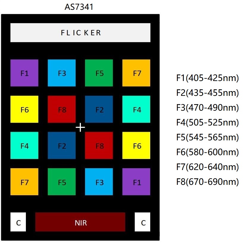
为了确保显示光谱分析数据的时候,对应光谱色条的颜色和上述色卡一致,使用PIL.Image直接从色卡图片中取得对应的颜色值备用显示。
行空板上的Python预装的pinpong库中,带有AS7341驱动库:pinpong.libs.dfrobot_as7341,可以很方便的引入操控AS7341。
AS7341的使用分为三部:
1. 初始化:as7341.begin()2. 开启测量:as7341.start_measure(0)、as7341.start_measure(1)3. 读取数据:as7341.read_spectral_data_one()、as7341.read_spectral_data_two()读取到的数据中,包含:adf1~adf8,及对应上述色卡的8个通道F1~F8。
读取到数据后,将8个数据的数值更新到屏幕上对应文本控件,再计算得出各通道对应的颜色,并更新对应色条的大小。
步骤7 实物展示
运行上述程序后,首先会显示AS7341色卡,并从中提取八通道对应的色值。
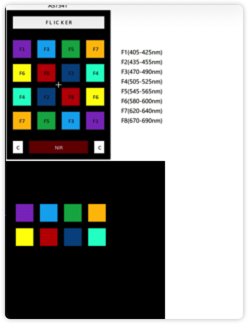
然后,会根据当前光纤情况,自动进行分析,并显示出来分析的结果:
当将手指覆盖在手机LED灯上时,人眼看到手指呈红色。
通过光线传感器,最终可以看到:主要颜色为F8(近红色),其次为F7(近深黄色),其他颜色占比很低。
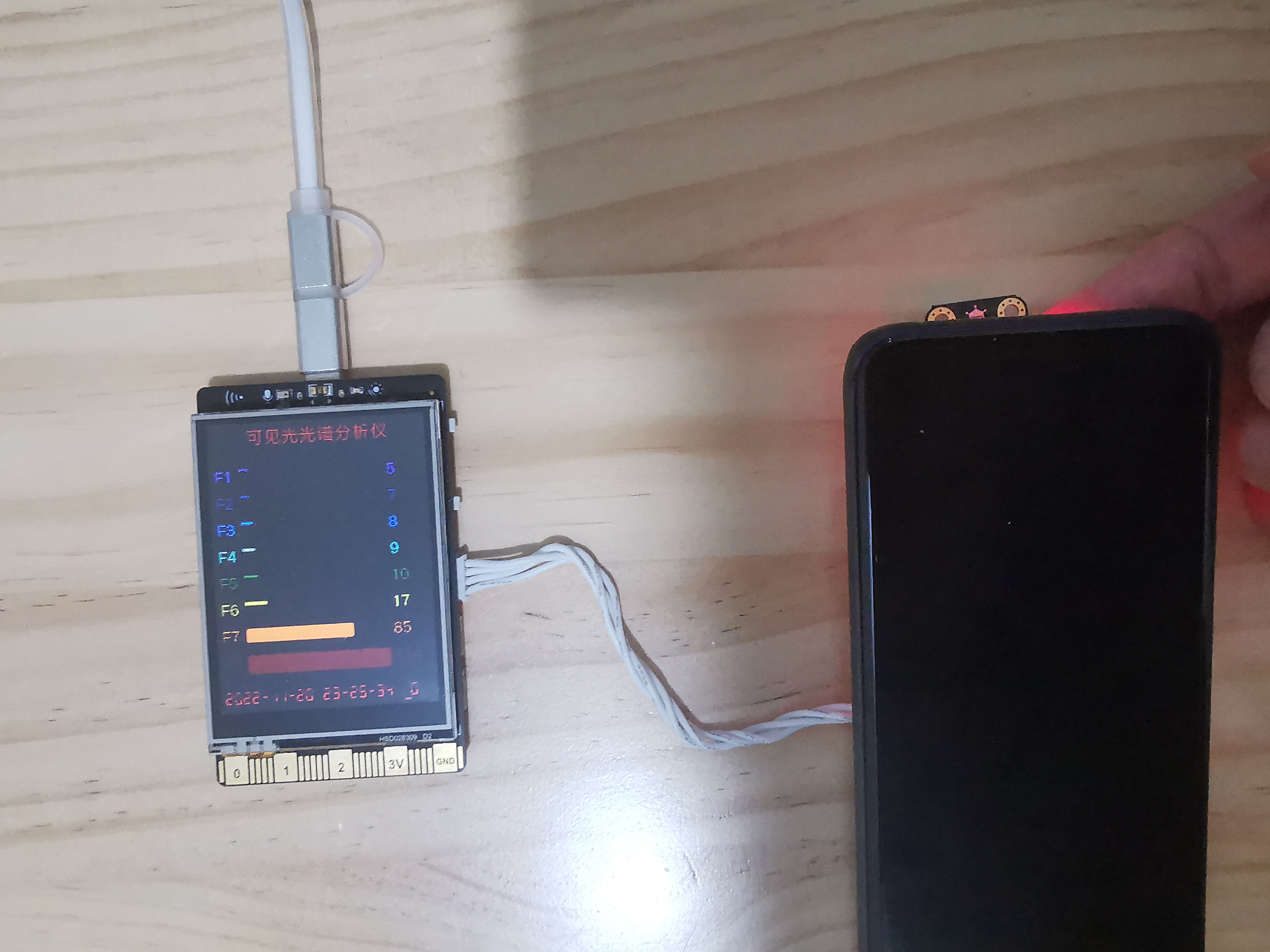
在不同的入射光线情况下,分析结果也会不同。
步骤8 总结
得益于行空板的良好设计和硬件库的完善支持,这个作品能够很好的完成,并且有较好的功能和效果。
这个作品,只是演示了一个比较基础的可见光谱分析的功能。根据实际情况,可以有很多用途,例如可以分析可溶于水的不同颜料的光谱,还可以分析水质的光谱,来监听污染程度,具有很好的实用价值!


 他的勋章
他的勋章

花生编程2023.01.21
不错
花生编程2023.01.21
不错
三春牛-创客2023.01.03
不错
三春牛-创客2023.01.03
厉害厉害
摸鱼的网民2022.12.16
好高级